Multipurpose switch circuit
A technology of switch circuit and switch control circuit, which is applied in the direction of electronic switches, electrical components, coding, etc., and can solve the problem of increasing buttons
- Summary
- Abstract
- Description
- Claims
- Application Information
AI Technical Summary
Problems solved by technology
Method used
Image
Examples
Embodiment Construction
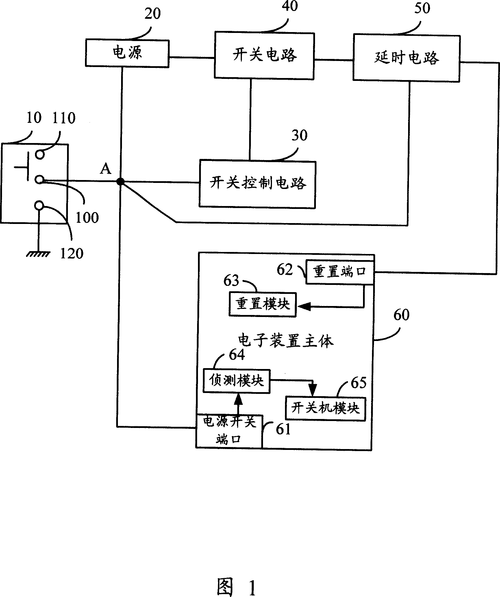
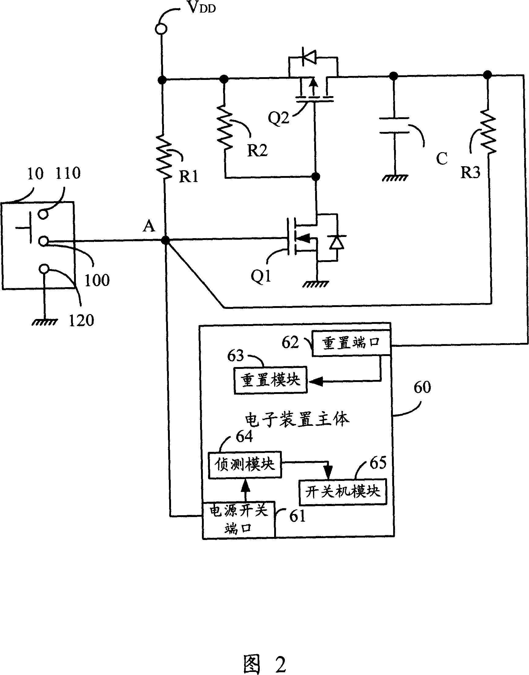
[0013] Please refer to FIG. 1 , which is a circuit block diagram of a specific embodiment of a multi-purpose switch circuit. A multi-purpose switch 10 operated by the user is an automatic reset switch. As shown in Figure 1, it is a double-contact automatic reset switch. Circuit 30, a delay circuit 50 and an electronic device main body 60 are all connected to a node A; a contact 110 (for convenience of description, hereinafter referred to as "left contact 110") of the double contact automatic reset switch is suspended ( 1) or be connected to a high potential (not shown), and the other contact 120 (hereinafter referred to as "right contact 120") is connected to a low potential, such as ground. In other embodiments, the multi-purpose switch 10 can also be a push-type automatic reset switch, one contact of the push-type automatic reset switch is grounded, and the other contact is connected to node A.
[0014] The electronic device main body 60 performs various actions according t...
PUM
 Abstract
Description
Claims
Application Information
 - R&D
- Intellectual Property
- Life Sciences
- Materials
- Tech Scout
- Unparalleled Data Quality
- Higher Quality Content
- 60% Fewer Hallucinations
Browse by: Latest US Patents, China's latest patents, Technical Efficacy Thesaurus, Application Domain, Technology Topic, Popular Technical Reports.
© 2025 PatSnap. All rights reserved.Legal|Privacy policy|Modern Slavery Act Transparency Statement|Sitemap|About US| Contact US: help@patsnap.com


