Automobile provided with braking parachute

A speed parachute, automobile technology, applied in the direction of vehicle parts, brakes, brake components, etc., can solve the problems of personal injury, vehicle scrapping, damage, etc., and achieve the effect of reducing traffic accidents

Inactive Publication Date: 2007-07-11
霍明远
View PDF0 Cites 8 Cited by
  • Summary
  • Abstract
  • Description
  • Claims
  • Application Information

AI Technical Summary

Problems solved by technology

Often on the expressway, several cars or even dozens of cars rear-end collision accidents occur, causing personal casualties and vehicle scrapping or damage
In the past, most of

Method used


Image

  • Automobile provided with braking parachute

Examples


Example Embodiment

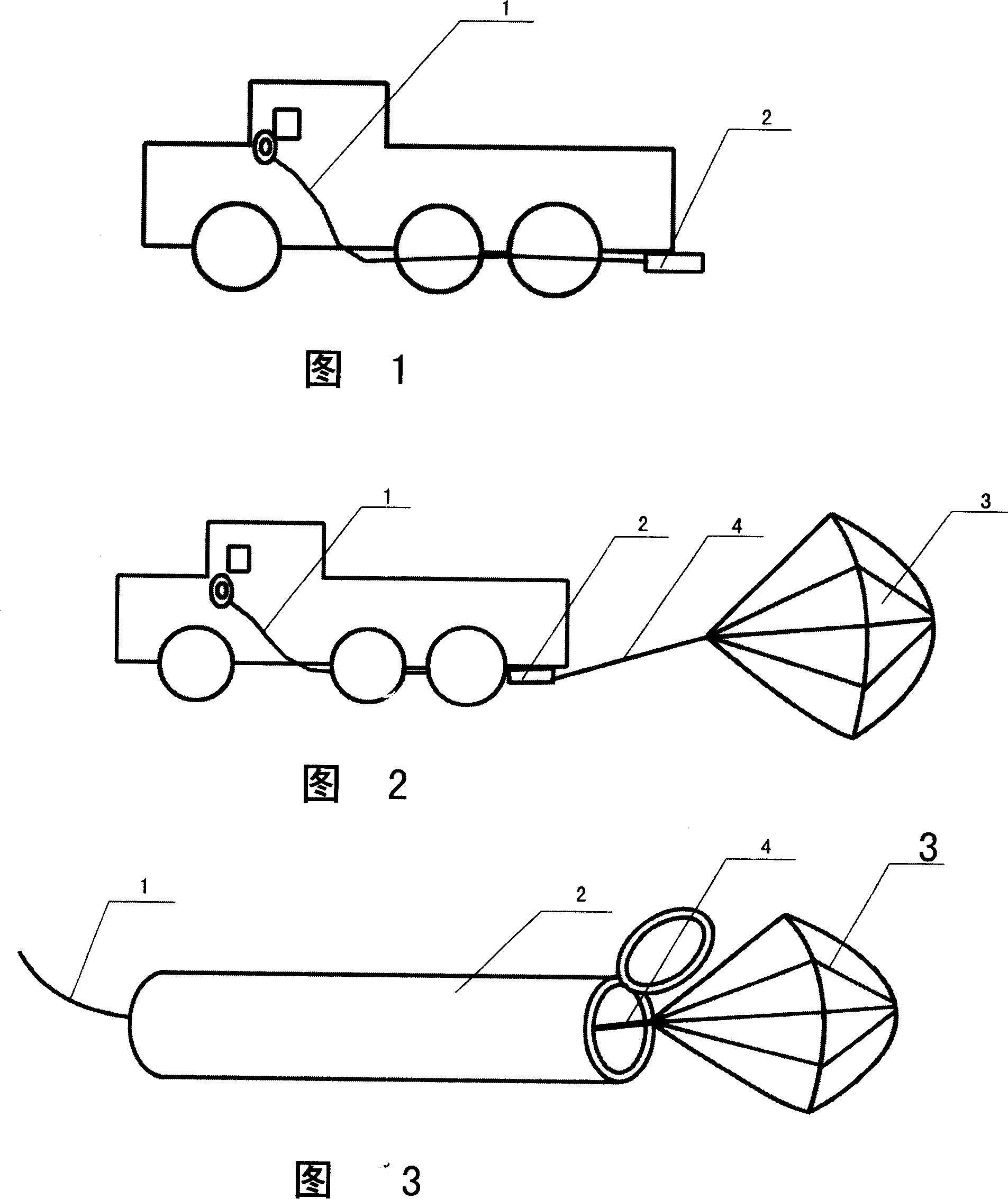
[0011] According to Fig. 1, Fig. 2, shown in Fig. 3: a kind of car with deceleration parachute, it mainly is made up of engine, cab control system, chassis, wheel, car body, and it is provided with deceleration parachute device, and deceleration parachute device is mainly Including control switch, conduit 1, metal bobbin 2, umbrella body 3 and connecting wire 4; when the umbrella body 3 is in a contracted state, it is inside the metal bobbin 2; there is compressed gas in the conduit 1, and the source of compressed air is from the automobile brake airway Lead a way back, also can add gas storage device or inflation device in metal bobbin 2, be provided with connecting wire 4 on umbrella body 3 sides, one end of connecting wire 4 links to each other with cable, and the other end is fixed with metal bobbin 2. The metal bobbin 2 is arranged on the chassis at the rear of the car; the umbrella body 3 is spiral in the metal bobbin 2, and the barrel wall is a spiral concave thread. Whe...


PUM


Abstract

The invention relates to a vehicle with damping umbrella, formed by engine, cabin control system, chassis, wheels, and main body, wherein the damping umbrella mainly comprises control switch, tube 1, metal cylinder 2, umbrella 3, and connecting wire 4; the umbrella 3 is contracted into the metal cylinder 2; tube 1 contains compressed air; the metal cylinder can air container or aerator; the edge of umbrella 3 has connecting wire 4; another end of wire 4 is connected to the fixer of metal cylinder 2; the metal cylinder 2 is at the chassis of vehicle tail; the cabin has control switch of damping umbrella. When vehicle has emergence, driver can use invention to decelerate the vehicle.

Description

technical field [0001] The invention relates to a device capable of helping emergency deceleration of a car in distress. Background technique [0002] Nowadays, when there are more and more highways and the speed of cars is getting faster and faster, the safety of cars is becoming more and more urgent. Often on the expressway, the accident of rear-end collision of several cars or even dozens of cars takes place, causing personal casualties and vehicle scrapping or damage. In the past, most of the car safety systems were on the brake pads, ABC, and air bag body protection. The effect was really good, but for major collision accidents, it often could not solve the problem. Contents of the invention [0003] In order to solve the above problems, the present invention provides a car with a parachute in case of emergency, which uses air resistance to reduce the speed of the car. [0004] The purpose of the present invention is achieved like this: a kind of automobile with par...

Claims


Application Information

Patent Timeline
IPC IPC(8): B60T1/16
Inventor 霍明远
Owner 霍明远
Why Eureka
Try Eureka