Check patentability & draft patents in minutes with Patsnap Eureka AI!

Linearly-actuated magnetocaloric heat pump

a magnetocaloric heat pump and linear actuator technology, applied in the field of heat pump systems, can solve the problems of not operating at 45 percent or less of the maximum theoretical carnot cycle efficiency, the range of ambient temperatures over which certain refrigerant-based systems can operate may be impractical for certain locations, and the difficulty of practical and cost-competitive use of an mcm

Active Publication Date: 2018-06-26
HAIER US APPLIANCE SOLUTIONS INC
View PDF146 Cites 33 Cited by
  • Summary
  • Abstract
  • Description
  • Claims
  • Application Information

AI Technical Summary

Benefits of technology

The present invention is a heat pump system that includes a magnet assembly and a regenerator housing with a plurality of stages. The heat pump system includes a cold side heat exchanger, a hot side heat exchanger, a first pump for circulating a working fluid between the cold side and hot side heat exchangers, and a second pump for circulating the working fluid between the cold side and hot side heat exchangers. The heat pump system also includes a bearing assembly with a regenerator housing as a component. The heat pump system has improved performance and efficiency compared to conventional heat pumps.

Problems solved by technology

While improvements have been made to such heat pump systems that rely on the compression of fluid refrigerant, at best such can still only operate at about 45 percent or less of the maximum theoretical Carnot cycle efficiency.
The range of ambient temperatures over which certain refrigerant-based systems can operate may be impractical for certain locations.
Other challenges with heat pumps that use a fluid refrigerant exist as well.
Challenges exist to the practical and cost competitive use of an MCM, however.
Currently proposed equipment may require relatively large and expensive magnets, may be impractical for use in e.g., appliance refrigeration, and may not otherwise operate with enough efficiency to justify capital cost.

Method used


Image

  • Linearly-actuated magnetocaloric heat pump
  • Linearly-actuated magnetocaloric heat pump
  • Linearly-actuated magnetocaloric heat pump

Examples


Embodiment Construction

[0045]Reference now will be made in detail to embodiments of the invention, one or more examples of which are illustrated in the drawings. Each example is provided by way of explanation of the invention, not limitation of the invention. In fact, it will be apparent to those skilled in the art that various modifications and variations can be made in the present invention without departing from the scope or spirit of the invention. For instance, features illustrated or described as part of one embodiment can be used with another embodiment to yield a still further embodiment. Thus, it is intended that the present invention covers such modifications and variations as come within the scope of the appended claims and their equivalents.

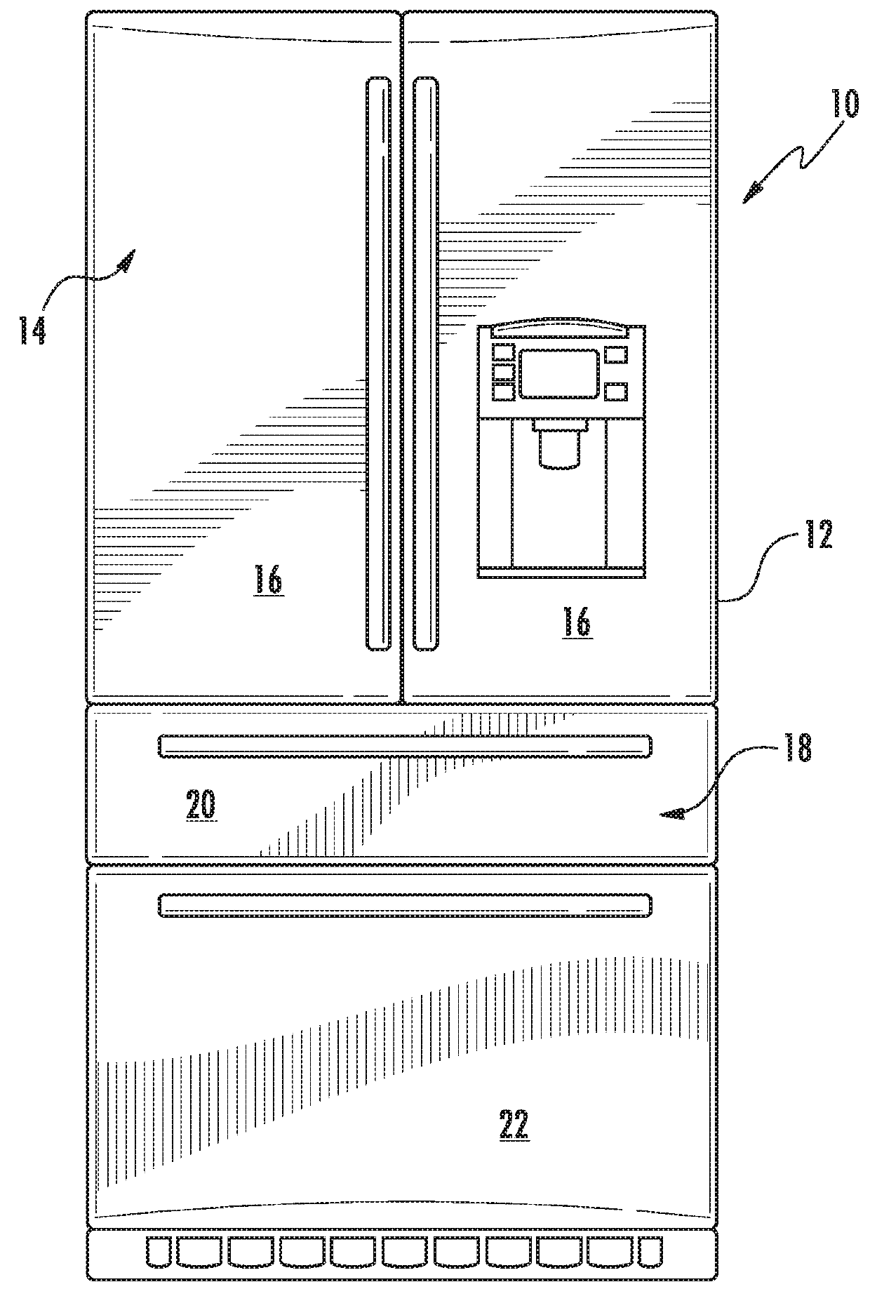
[0046]Referring now to FIG. 1, an exemplary embodiment of a refrigerator appliance 10 is depicted as an upright refrigerator having a cabinet or casing 12 that defines a number of internal storage compartments or chilled chambers. In particular, refrigerato...


PUM


Abstract

A heat pump includes a magnet assembly which creates a magnetic field, and a regenerator housing which includes a body defining a plurality of chambers, each of the plurality of chambers extending along a transverse direction orthogonal to the vertical direction. The heat pump further includes a plurality of stages, each of the plurality of stages including a magnetocaloric material disposed within one of the plurality of chambers and extending along the transverse direction between a first end and a second end.

Description

FIELD OF THE INVENTION[0001]The subject matter of the present disclosure relates generally to a heat pump system that uses magnetocaloric materials to exchange heat with a circulating heat transfer fluid.BACKGROUND OF THE INVENTION[0002]Conventional refrigeration technology typically utilizes a heat pump that relies on compression and expansion of a fluid refrigerant to receive and reject heat in a cyclic manner so as to effect a desired temperature change or i.e. transfer heat energy from one location to another. This cycle can be used to provide e.g., for the receiving of heat from a refrigeration compartment and the rejecting of such heat to the environment or a location that is external to the compartment. Other applications include air conditioning of residential or commercial structures. A variety of different fluid refrigerants have been developed that can be used with the heat pump in such systems.[0003]While improvements have been made to such heat pump systems that rely on...

Claims


Application Information

Patent Timeline
Patent Type & Authority Patents(United States)
IPC IPC(8): F25B21/00F25B41/04F25D17/02F25D11/02
CPCF25B21/00F25B41/04F25D11/02F25D17/02F25B2321/0023F25B2321/0021F25B2321/0022Y02B30/00
Inventor BENEDICT, MICHAEL ALEXANDERBEERS, DAVID G.SCHORK, BRIAN MICHAELSCHROEDER, MICHAEL GOODMAN
Owner HAIER US APPLIANCE SOLUTIONS INC
Features
  • R&D
  • Intellectual Property
  • Life Sciences
  • Materials
  • Tech Scout
  • Unparalleled Data Quality
  • Higher Quality Content
  • 60% Fewer Hallucinations
Learn More