Broadcast channel based estimation of frequency offset

a frequency offset and broadcast channel technology, applied in the field of estimating a frequency offset, can solve the problems of mtc device not being able to receive all, mtc device may be problematic, mtc device may not be able to estimate all, etc., and achieve the effect of efficient coordination of frequency offset measurement and efficient estimation of frequency offs

Active Publication Date: 2018-06-26
SONY CORP
View PDF3 Cites 6 Cited by
  • Summary
  • Abstract
  • Description
  • Claims
  • Application Information

AI Technical Summary

Benefits of technology

[0022]In the above embodiments, the at least one broadcast signal may comprise a Physical Broadcast Channel (PBCH), a PSS (Primary Synchronization Signal), and a Secondary Synchronization Signal (SSS) as specified for the LTE radio technology. Since these signals are transmitted in a narrow frequency band covering 72 central subcarriers within the total frequency band of the LTE radio technology, they are suitable for efficient estimation of the frequency offset even if the radio device supports only data transmission in a narrow frequency band. In MTC, the PBCH can be repeated many times. Thus, all or some parts of it can be used for precise frequency offset estimation / measurement purposes. The measurement time interval allows for efficient coordination of the frequency offset measurement with the data transmission operation of the radio device. In particular, both the radio device and the base station may be made aware of the measurement interval so that it can be avoided that the frequency offset measurement interferes with the data transmission.

Problems solved by technology

In view of the operating bandwidth being is smaller than the total bandwidth offered by the eNB, frequency offset measurements based on CRS may be problematic in the case of an MTC device.
Specifically, due to the limited bandwidth the MTC device is not able to receive all CRS which are distributed over the entire bandwidth offered by the eNB.

Method used


Image

  • Broadcast channel based estimation of frequency offset
  • Broadcast channel based estimation of frequency offset
  • Broadcast channel based estimation of frequency offset

Examples


Embodiment Construction

[0033]In the following, exemplary embodiments of the invention will be described in more detail. It has to be understood that the following description is given only for the purpose of illustrating the principles of the invention and is not to be taken in a limiting sense. Rather, the scope of the invention is defined only by the appended claims and is not intended to be limited by the exemplary embodiments described hereinafter.

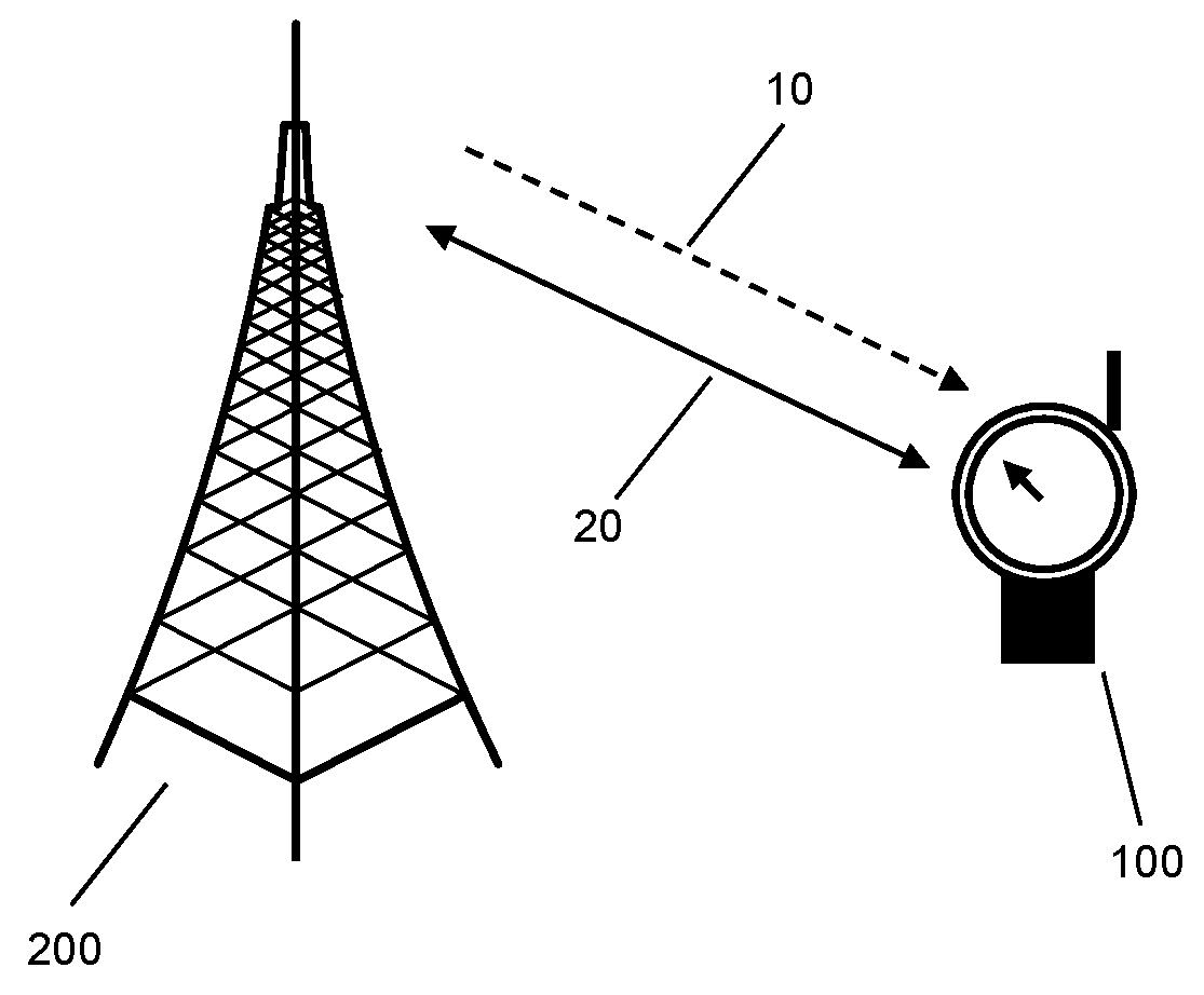
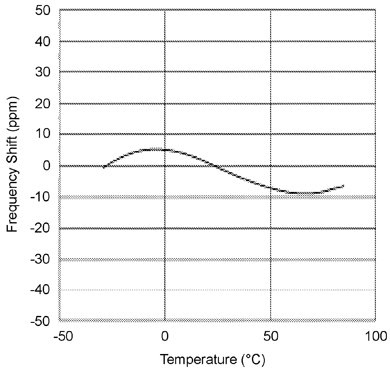
[0034]The illustrated embodiments relate to a scenario in which a radio device applies a carrier frequency for data transmission between the radio device and a base station of the cellular network, which may deviate from a frequency of a carrier signal as received from the base station, although these two frequencies should be nominally the same. Such frequency offset may relate to temperature dependent variations of characteristics of an oscillator from which the carrier frequency is derived by the radio device, to aging of the oscillator, to phase noise, t...


PUM


Abstract

A radio device applies a carrier frequency for transmission of data between the radio device and a base station of a cellular network. Further, the radio device configures a measurement time interval in which the radio device temporarily switches from the transmission of data to receiving at least one broadcast signal conveying system information from the base station. Based on the received at least one broadcast signal, the radio device estimates an offset of the carrier frequency as applied by the radio device to a frequency of a carrier signal as received from the base station.

Description

RELATED APPLICATION DATA[0001]This application is a continuation-in-part of International Patent Application No. PCT / EP2015 / 072175, filed Sep. 25, 2015, the disclosure of which is incorporated herein by reference in its entirety.FIELD OF THE INVENTION[0002]The present invention relates to methods of estimating a frequency offset between a base station of a cellular network and a radio device operated in the cellular network, and to corresponding devices.BACKGROUND OF THE INVENTION[0003]In cellular networks, such as a cellular network based on the LTE (Long Term Evolution) radio technology specified by 3GPP (3rd Generation Partnership Project), it is typically required that a frequency utilized by a radio receiver / transmitter in a user equipment (UE) matches a frequency utilized by a radio receiver / transmitter in a base station of the cellular network, in the LTE radio technology referred to as eNB (evolved Node B). To meet this requirement, the UE may perform frequency offset measur...

Claims


Application Information

Patent Timeline
Patent Type & Authority Patents(United States)
IPC IPC(8): H04W24/00H04W28/20H04J11/00H04W72/04H04W76/00H04L27/26H04W24/10H04W88/02H04W88/08
CPCH04W28/20H04J11/00H04L27/2657H04L27/2673H04W76/40H04W72/048H04W24/10H04W88/02H04W88/08H04W72/51
Inventor ZANDER, OLOFPRIYANTO, BASUKIBEALE, MARTINWONG, SHIN HORNG
Owner SONY CORP
Why Eureka
Try Eureka