
Printing apparatus and printing method

a printing apparatus and printing method technology, applied in the direction of printing, printing, other printing apparatus, etc., can solve the problems of increasing the cost of the apparatus, deteriorating the printing accuracy, and complicated structure of the apparatus, so as to improve the printing accuracy

Active Publication Date: 2018-07-10
FUJIFILM CORP
View PDF13 Cites 0 Cited by
  • Summary
  • Abstract
  • Description
  • Claims
  • Application Information

AI Technical Summary

Benefits of technology

The invention provides a printing apparatus and method with improved printing accuracy without adding complexity to the structure of the apparatus.

Problems solved by technology

Further, the pattern forming apparatus disclosed in JP2008-258249A finds a deviation from the ideal position of the first pattern, but does not perform the correction and the like of the pattern.
There is a problem that printing accuracy deteriorates when an error occurs during the formation of a pattern.
Since the check roller is required in JP2014-61653A and JP2010-91965A, the structure of the apparatus becomes complicated.
For this reason, there is a problem that the cost of the apparatus is increased.

Method used


Image

  • Printing apparatus and printing method
  • Printing apparatus and printing method
  • Printing apparatus and printing method

Examples


Embodiment Construction

[0043]A printing apparatus and a printing method of the invention will be described in detail below on the basis of preferred embodiments shown in the accompanying drawings. The invention is not limited to the printing apparatus and the printing method of embodiments to be described below.

[0044]“˜” representing the range of a numerical value to be described below includes numerical values that are written on both sides of “˜”. For example, a fact that E is in the range of a numerical value α˜a numerical value β means that the range of E is a range including the numerical value α and the numerical value β, and is expressed as “α≤ε≤β” by mathematical symbols.

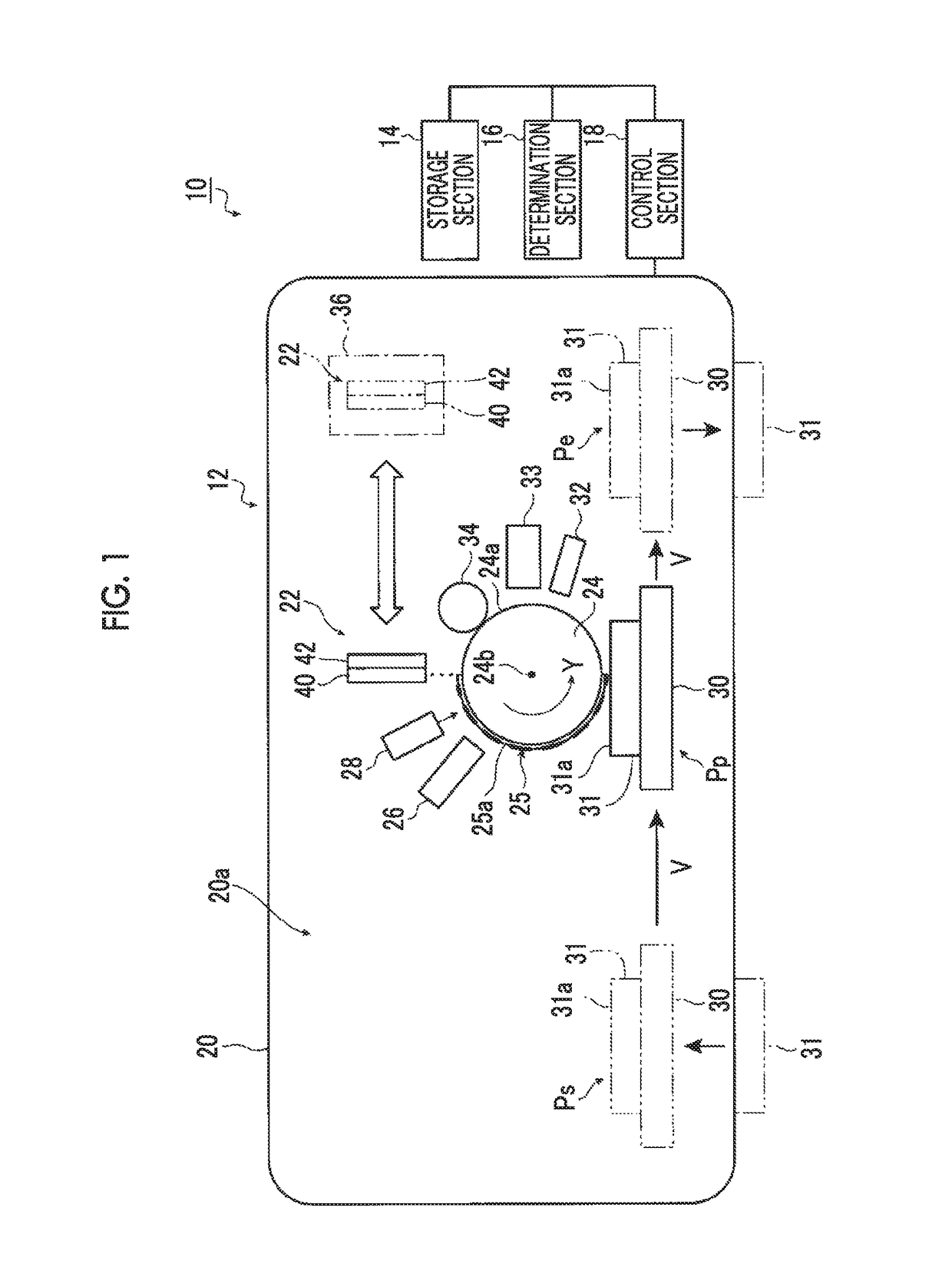
[0045]FIG. 1 is a schematic diagram showing a printing apparatus of an embodiment of the invention.

[0046]As shown in FIG. 1, the printing apparatus 10 includes a printing apparatus body 12, a storage section 14, a determination section 16, and a control section 18.

[0047]The printing apparatus body 12 is to form a predetermined pat...


PUM


Abstract

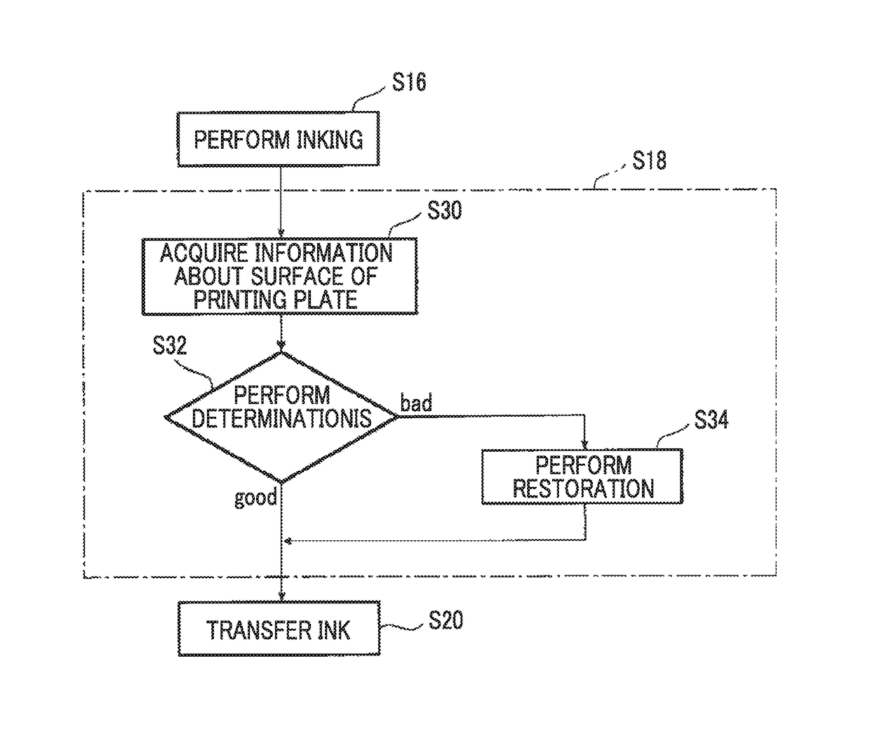
A printing apparatus applies ink to a surface of a printing plate in the shape of a predetermined pattern and then transfers the ink to a substrate. The printing apparatus includes: an image recording section that applies the ink to the surface of the printing plate; a plate surface observation unit that acquires information about the surface of the printing plate; a storage section that stores information about a reference shape serving as a reference of the surface of the printing plate; and a determination section that compares the information about the reference shape stored in the storage section with the information about the surface of the printing plate, which is obtained by the plate surface observation unit, and determines whether or not the surface of the printing plate to which the ink has been applied is present in a predetermined range of the reference shape.

Description

CROSS-REFERENCE TO RELATED APPLICATIONS[0001]This application is a Continuation of PCT International Application No. PCT / JP2015 / 079593 filed on Oct. 20, 2015, which claims priority under 35 U.S.C. § 119(a) to Japanese Patent Application No. 2014-230281 filed on Nov. 13, 2014. The above application is hereby expressly incorporated by reference, in its entirety, into the present application.BACKGROUND OF THE INVENTION[0002]1. Field of the Invention[0003]The present invention relates to a printing apparatus and a printing method of which printing accuracy is improved without the complication of the structure of the apparatus, and more particularly, to a printing apparatus and a printing method that can be used to form a gate electrode, a source electrode, a drain electrode, wires, and the like of a thin-film transistor used in electronic paper and the like.[0004]2. Description of the Related Art[0005]In recent years, gate electrode, source electrodes, drain electrodes, and metal wiring...

Claims


Application Information

Patent Timeline
Patent Type & Authority Patents(United States)
IPC IPC(8): B41F9/00B41F9/06B41F35/02B41F33/00B41M1/10B41J2/01H01L21/288H01L29/66
CPCB41F9/003B41F9/061B41F33/0027B41F35/02B41J2/01B41M1/10H01L21/288H01L29/66742B41J2002/012B41P2200/10B41P2235/24B41M1/34B41M1/06B41F9/00B41F17/26H01L27/1292
Inventor KODAMA, KENICHI
Owner FUJIFILM CORP
Learn More