Die casting device

a technology of die casting and casting products, which is applied in the field of die casting devices, can solve the problems of product quality deterioration, difficulty in improving feeding accuracy, and reducing the temperature of molten metal, so as to reduce the effect of abrasion and vibration, and improve the quality of casting products

Inactive Publication Date: 2015-06-23
TOYOTA JIDOSHA KK
View PDF21 Cites 0 Cited by
  • Summary
  • Abstract
  • Description
  • Claims
  • Application Information

AI Technical Summary

Benefits of technology

[0011]The present invention provides a die casting device that can maintain, with a simple configuration, the quality of casting products, the accuracy of molten-metal feeding into the injection sleeve, and the durability of the die casting device, and also reduce the effect of abrasion and vibration at the time of injection.
[0017]The die casting device of the present invention can maintain, with a simple configuration, the quality of casting products, the accuracy of molten-metal feeding into the injection sleeve, and the durability of the die casting device, and also reduce the effect of abrasion and vibration at the time of injection.

Problems solved by technology

However, in the configuration disclosed in JP 2003-245768 A, as it is difficult to adjust the amount of ladled molten metal, it is difficult to improve the feeding accuracy.
In addition, as molten metal touches the atmosphere at the time of feeding from the ladle into the sleeve, there are problems that the temperature of the molten metal decreases, and / or the product quality deteriorates due to gas such as dissolved hydrogen and an oxidized film produced in the molten metal.
However, because the injection sleeve is fed with molten metal of high temperature, deformation is incurred in the injection sleeve due to the heat of the molten metal, which tends to cause vibrations at the time of injection.
In the configurations disclosed in JP 4-258357 A and JP 2002-239708 A, there are problems that the feeding pipe directly joined to the injection sleeve, and / or its junction are damaged due to abrasion and / or vibration at the time of injection.
In addition, there is a possibility that the strength of the cover is insufficient with respect to the heat of the molten metal at the time of molten-metal feeding and / or the pressure at the time of decompressing a cavity, and that the cover is damaged.

Method used


Image

  • Die casting device
  • Die casting device
  • Die casting device

Examples


Embodiment Construction

[0022]It should be noted that the scope of the invention is not limited to the following embodiment but broadly contains the whole technical idea that is described in this specification and the drawings.

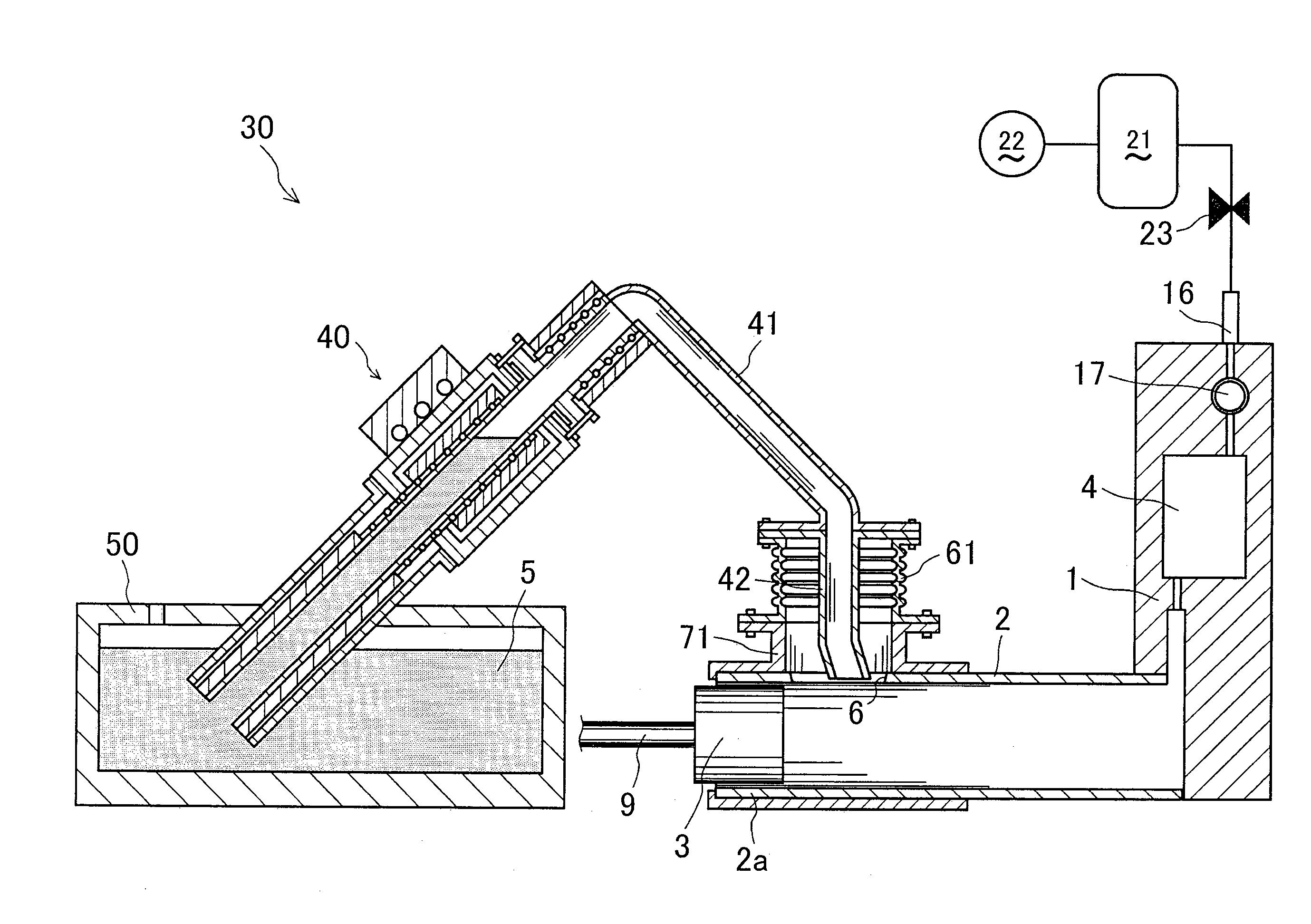
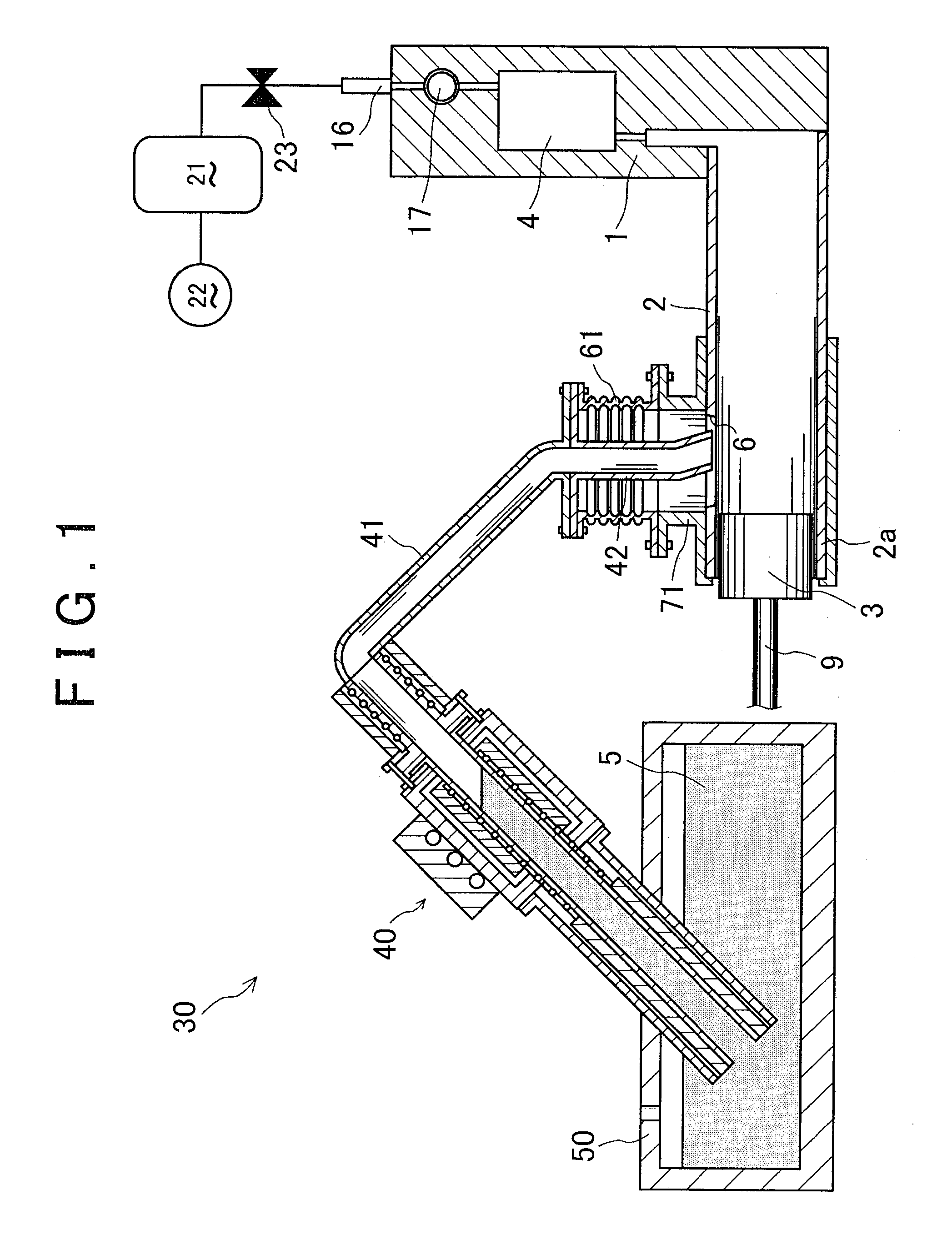
[0023]The die casting device 30 according to one embodiment of the present invention will be described with reference to FIG. 1. In this specification, descriptions will be made in a manner that the direction from the left side to the right side (from the left side to the right side of the die casting device 30) and the direction from the right side to the left side in FIG. 1 are referred to as “right side direction” and “left side direction”, respectively.

[0024]As shown in FIG. 1, a die 1 of the die casting device 30 has a cavity 4 formed therein, and an injection sleeve 2 having a substantially cylindrical shape is attached to the die 1 in a manner to be projected leftward from the die 1 and to communicate with the cavity 4. In the injection sleeve 2, an injection tip 3 having a sh...


PUM

PropertyMeasurementUnit
angleaaaaaaaaaa
thermalaaaaaaaaaa
pressureaaaaaaaaaa

Abstract

A die casting device includes a die including a cavity; an injection sleeve including a feeding orifice; an injection tip provided at the distal end of a support shaft, and configured to be slidable in an axial direction within the injection sleeve by inserting the support shaft into the injection sleeve; a decompression device; a molten-metal holding furnace including a space to store molten metal; a pump pumping up the molten metal from the molten-metal holding furnace; and a feeding pipe including a first end connected to the pump and a second end. The feeding pipe is joined to the injection sleeve through a relay pipe including a vibration absorption portion, the molten metal is fed into the injection sleeve from the molten-metal holding furnace through the feeding pipe by the pump, and is pushed out of the injection sleeve by the injection tip, and the molten metal is injected into the cavity decompressed by the decompression device.

Description

BACKGROUND OF THE INVENTION[0001]1. Field of the Invention[0002]The present invention relates to a die casting device, specifically to a die casting technique, in which the cavity of a die is decompressed to conduct casting.[0003]2. Description of Related Art[0004]In conventional die casting, the following techniques are used, namely: feeding a predetermined amount of molten metal into an injection sleeve having a feeding orifice; after the feeding, moving an injection tip by drive means at a predetermined timing; and injecting the molten metal from the injection sleeve into the cavity of a die at high pressure (For example, refer to Japanese Patent Application Publication No. 2003-245768 (JP 2003-245768 A), Japanese Patent Application Publication No. 4-258357 (JP 4-258357 A), Japanese Patent Application Publication No. 2002-239708 (JP 2002-239708 A), and Japanese Patent Application Publication No. 2004-167499 (JP 2004-167499 A)).[0005]In the die casting device disclosed in JP 2003-...

Claims


Application Information

Patent Timeline
Patent Type & Authority Patents(United States)
IPC IPC(8): B22D17/14B22D17/30B22D17/04
CPCB22D17/14B22D17/30B22D17/04
Inventor KIKUCHI, MAKOTO
Owner TOYOTA JIDOSHA KK
Why Eureka
Try Eureka