Eyeglass positioning device

a positioning device and eyeglass technology, applied in the field of eyeglass positioning devices, can solve the problems of unobtrusiveness and discreteness, and achieve the effects of less distortion, less distortion, and greater flexibility in the amount of height adjustmen

Inactive Publication Date: 2018-07-10
VISUALIGN
View PDF56 Cites 4 Cited by
  • Summary
  • Abstract
  • Description
  • Claims
  • Application Information

AI Technical Summary

Benefits of technology

[0010]This invention provides a simple, universal eyeglass positioning device that may be used with many different types, styles, and sizes of multifocal eyeglass frames. It is easy to position relative to the user's face and the eyeglass frame, easy to remove when use is not needed, and is unobtrusive and discrete when in use. According to one preferred embodiment, an eyeglass positioning device comprises a generally U-shaped connector with support arms extending from each end of the connector. The eyeglass positioning device simply sits on the user's nose. The frame of the multifocal eyeglasses rests on some part of the eyeglass positioning device, which may vary depending on the frame style and size, allowing the device to be used with a variety of different eyeglasses and not requiring any specialized or modified frames. The thickness of the eyeglass positioning devices elevates the eyeglasses relative to the user's face to elevate the focal regions disposed at the mid-to-bottom region of the lenses into a line of sight with a natural head position for computer use.
[0011]According to another preferred embodiment, an eyeglass positioning device is capable of securely supporting an eyeglass frame without requiring any portion of the positioning device to attach or hook onto the frame. The exterior surface of the positioning device is preferably made of materials that are slip-resistant and that frictionally engage the eyeglasses frame or the nose pads of the eyeglasses to hold them in place. The interior surfaces of the positioning device are also preferably made of slip-resistant materials to keep the device from slipping on the user's nose.
[0012]According to another preferred embodiment, an eyeglass positioning device comprises a substantially U-shaped connector and two support arms that extend in a substantially perpendicular direction from each rearward end of the U-shaped connector. This preferred embodiment is capable of use in two different orientations. In a first orientation, the connector of the eyeglass positioning device sits on or near the bridge of the user's nose (or extends across the top of the user's nose) proximal to the eyes with the support arms extending down the sides of the nose toward the user's mouth (referred to herein as the upright position or orientation). In a second orientation, the connector sits on or near the bridge of the user's nose (or extends across the top of the user's nose) distal from the eyes with the support arms extending up the sides of the nose toward the user's eyes (referred to herein as the inverted position or orientation). The differing orientations provide more flexibility for use of the device with different styles and sizes of eyeglass frames and a user may find one orientation more comfortable than the other. No modification to the device is needed to switch between the first and second orientations; the device is simply placed on the user's face in one of the two orientations and can easily be removed, rotated and repositioned in the other orientation. Generally, the upright orientation is best suited for use with eyeglass frames having nose pads and the inverted orientation is best suited for use with eyeglass frames having no nose pads (saddle bridge). This is because nose pad frames are typically positioned slightly higher relative to the user's eyes than frames with a saddle bridge, so the inverted position aids in ensuring the saddle bridge frames make contact the positioning device. However, the orientation and placement of the frames relative to the positioning device may vary from user to user depending on the specific size and shape of the user's nose and eyeglass frame.

Problems solved by technology

It is easy to position relative to the user's face and the eyeglass frame, easy to remove when use is not needed, and is unobtrusive and discrete when in use.

Method used


Image

  • Eyeglass positioning device
  • Eyeglass positioning device
  • Eyeglass positioning device

Examples


Embodiment Construction

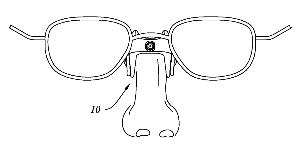
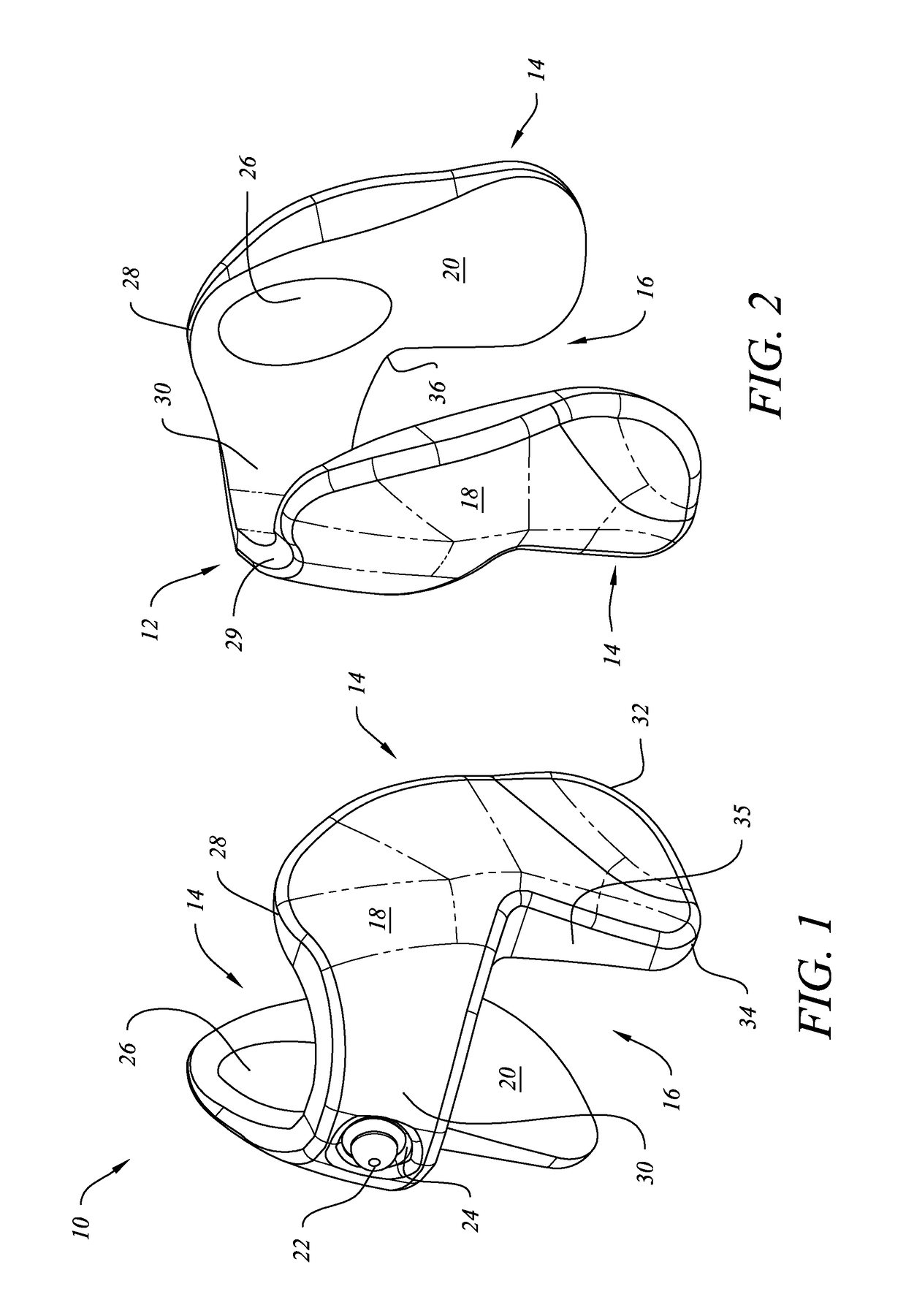
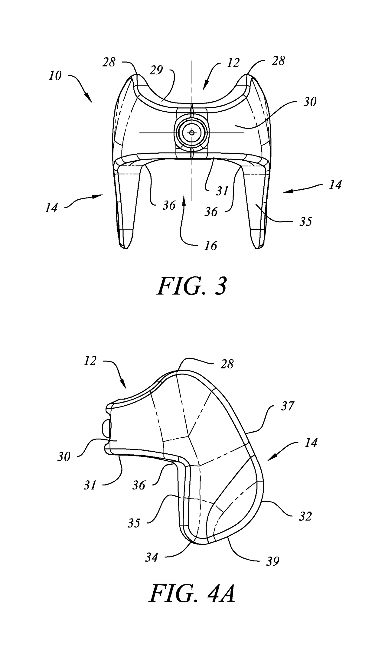
[0047]Referring to FIGS. 1-7, a preferred embodiment of an eyeglass positioning device 10 according to the invention is shown. In this embodiment, eyeglass positioning device 10 preferably comprises a generally U-shaped connector 12 and two support arms 14 (a right arm and a left arm) extending in a substantially perpendicular direction from each rearward end 33 of the U-shaped connector 12. Connector 12 and support arms 14 are preferably unitarily molded as a single body comprising an outer or exterior surface 18, a portion of which would contact an eyeglass frame in use, and an inner or interior surface 20, at least of portion of which contacts the user's nose when in use. An open area 16, into which a user's nose is placed, is formed on the interior surface side of positioning device 10 between connector 12 and support arms 14. Dashed lines on FIGS. 1-7 show contour or curvature on exterior surface 18.

[0048]Connector 12 preferably comprises a central portion 30 that forms a round...


PUM


Abstract

An eyeglass positioning device configured to be positioned between a user's nose and eyeglasses frame to elevate multifocal lenses relative to a user's eyes to bring an intermediate or near field of vision into a line of sight for use with certain activities, such as computer use, when the user's head is in an upright and normal head tilt position. The eyeglass positioning device preferably comprises a connector and two support arms that simply sit on a user's nose in either an upright or an inverted orientation, providing greater flexibility of use and comfort. The eyeglass positioning device may be used with a variety of shapes, styles, and sizes or eyeglass frames without requiring attachment to the frames or obstructing the field of view through the lenses. The eyeglass positioning device may include a visual or tactile indicator to aid in placing the device on a user's nose.

Description

CROSS-REFERENCE TO RELATED APPLICATION[0001]This application claims the benefit of U.S. Provisional Application Ser. No. 62 / 011,952 filed on Jun. 13, 2014.BACKGROUND OF THE INVENTION[0002]1. Field of the Invention[0003]This invention relates to device to temporarily elevate the position of eyeglasses having multifocal lenses relative to a user's eyes for proper visual and head alignment for certain activities, such as computer use.[0004]2. Description of Related Art[0005]Multifocal eyeglasses have been used for many years to provide different focal points to correct a user's vision for different activities, such as close-up reading or viewing a movie at a distance. These types of eyeglasses include bifocals, trifocals, and progressive no-line lenses. For certain activities, a user must adjust his or her head position to bring the portion of the glasses having the required focal point into the line of vision for the activity. This can cause neck and shoulder discomfort and headaches....

Claims


Application Information

Patent Timeline
Patent Type & Authority Patents(United States)
IPC IPC(8): G02C5/12G02C5/00
CPCG02C5/124G02C5/126G02C5/128G02C5/122G02C5/00
Inventor HAMILTON, JAMES D.GARY, LONNIE F.FILLIPP, STEPHEN L.
Owner VISUALIGN
Why Eureka
Try Eureka