Zero-wall clearance linkage mechanism with power seat drive

a technology of power seat drive and linkage mechanism, which is applied in the direction of reclining chairs, domestic applications, chairs, etc., can solve the problems of reducing the service life of the linkage mechanism. , to achieve the effect of efficient and cost-effectiv

Inactive Publication Date: 2018-07-17
L & P PROPERTY MANAGEMENT CO
View PDF28 Cites 7 Cited by
  • Summary
  • Abstract
  • Description
  • Claims
  • Application Information

AI Technical Summary

Benefits of technology

[0007]Embodiments seek to provide a simplified linkage mechanism that can be assembled to a motor and that can be adapted to essentially any type of seating unit. In an exemplary embodiment, the compact motor in concert with the linkage mechanism can achieve full movement of the seating unit between the closed, extended, and reclined positions. The motor may be employed in an efficient and cost-effective manner to adjust the linkage mechanism and is coupled primarily to the seat mounting plate.

Problems solved by technology

However, these seating units require relatively complex linkage mechanisms to afford this capability.
The complex linkage assemblies limit certain design aspects when incorporating automation, as well as adding weight and cost to the mechanism.

Method used


Image

  • Zero-wall clearance linkage mechanism with power seat drive
  • Zero-wall clearance linkage mechanism with power seat drive
  • Zero-wall clearance linkage mechanism with power seat drive

Examples


Embodiment Construction

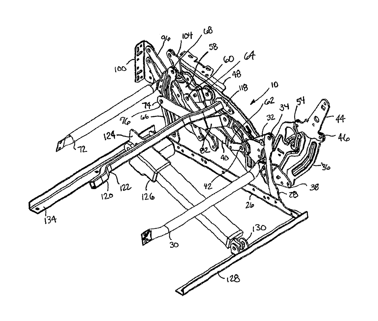
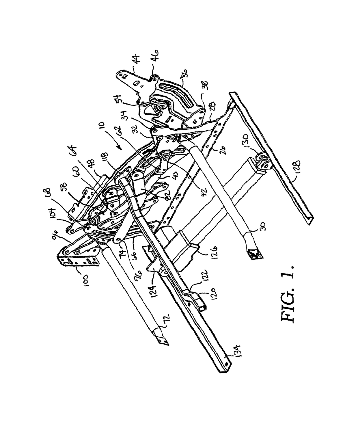
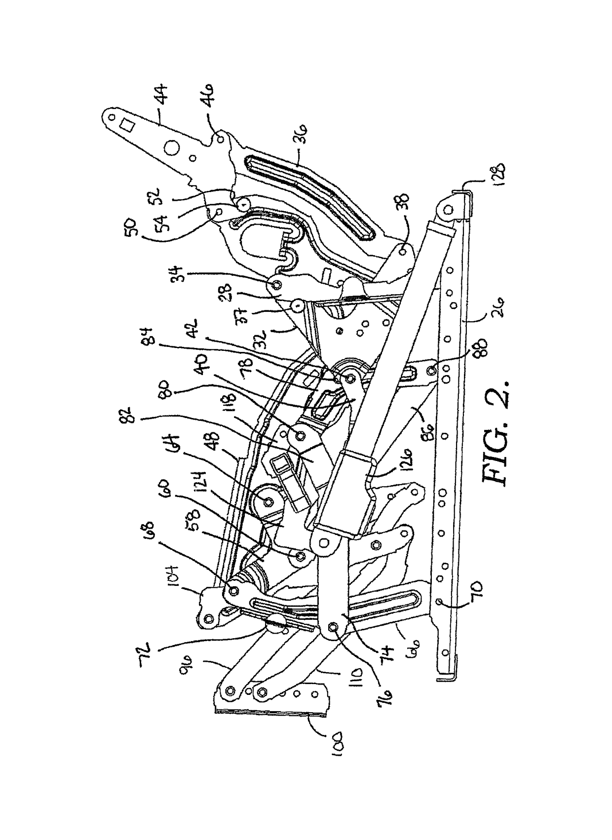
[0029]FIGS. 1-9 illustrate a first embodiment of a mechanism 10 for use on a motion seating unit 12, as shown in FIG. 19. Seating unit 12 has a seat 14, a backrest 16, legs 18, an ottoman 20, and a pair of opposed arms 22. The mechanism 10 couples the seat 14, the backrest 16, and the ottoman 20 together to move the seating unit 12 between closed, TV, and fully reclined positions, as is more fully described below.

[0030]As shown in FIGS. 1, 4, and 7, mechanism 10 is adjustable to three basic positions: a closed position (FIG. 1), an extended position (i.e., TV position) (FIG. 4), and a reclined position (FIG. 7). Additionally, only one side of mechanism 10 is shown, with the other side being a mirror-image of the side shown and described. FIG. 1 depicts the mechanism 10 adjusted to the closed position, which is a normal, non-reclined sitting position with the seat 14 in a generally horizontal position and the backrest 16 generally upright and in a substantially perpendicular position...


PUM


Abstract

A seating unit that includes a linkage mechanism adapted to adjust between closed, extended, and reclined positions is provided. The linkage mechanism includes a linear actuator primarily coupled to a seat mounting plate for carrying out automated adjustment of the linkage assembly.

Description

CROSS-REFERENCE TO RELATED APPLICATIONS[0001]None.STATEMENT REGARDING FEDERALLY SPONSORED RESEARCH OR DEVELOPMENT[0002]None.BACKGROUND OF THE INVENTION[0003]The present invention relates broadly to motion upholstery furniture designed to support a user's body in an essentially seated disposition. Motion upholstery furniture includes recliners, incliners, sofas, love seats, sectionals, theater seating, traditional chairs, and chairs with a moveable seat portion, such furniture pieces being referred to herein generally as “seating units.” More particularly, the disclosure relates to an improved linkage mechanism for use on motorized chairs and driven primarily from the seat mounting plate. The improved linkage mechanism accomplishes a zero-wall configuration with fewer parts and a more simplified assembly than existing mechanisms.[0004]Reclining seating units exist that allow a user to extend a footrest forward and to recline a backrest rearward relative to a seat. These existing seat...

Claims


Application Information

Patent Timeline
Patent Type & Authority Patents(United States)
IPC IPC(8): A47C1/035A47C1/032A47C1/0355
CPCA47C1/03211A47C1/0355
Inventor LAWSON, GREGORY M.
Owner L & P PROPERTY MANAGEMENT CO
Why Eureka
Try Eureka