Fire door lock

a door lock and fire technology, applied in building locks, construction, building construction, etc., can solve the problems of fire spreading and inconvenience for users, and achieve the effect of reducing the risk of fir

Active Publication Date: 2018-07-24
THASE ENTERPRISE CO LTD
View PDF4 Cites 0 Cited by
  • Summary
  • Abstract
  • Description
  • Claims
  • Application Information

AI Technical Summary

Benefits of technology

[0010]An objective of the present invention is to provide a fire door lock which allows a user to press a handle in a vertical direction with respect to a first door mounted with the fire door lock to activate a locking bolt in a comfortable manner to open the first door.
[0011]Another objective of the present invention is to provide a fire door lock which allows the locking bolt to extend from a lock housing to be directly inserted into a hole of the locking bolt formed on an inner side of a door frame, such that when the door lock is engaged, the locking bolt cannot be easily damaged by vandals, thereby increasing the security of the door lock.
[0012]In order to achieve the above and other objectives, the present invention provides a fire door lock, specifically featuring the improvement on the pressing handle of the fire door lock, which allows a first opening unit thereof to be located inside a fire door mounted with the lock and to activate a locking bolt of the lock to move. Moreover, a second opening unit laterally located on the fire door has a pressing handle coupled with an actuating block for operating the locking bolt. When the pressing handle is pushed and pressed, the actuating block activates an actuating rod and a linking arm to move horizontally. One end of the linking arm is coupled to a driving lever, and driving lever drives the linking arm to swing. One end of the driving lever has a pulley extending into the first opening unit to activate a locking bolt base connected to the locking bolt to move horizontally. As a result, the locking bolt is accordingly adapted to extend from or retract into the first opening unit in a horizontal direction to facilitate the release or engagement of the lock.
[0013]Furthermore, the first opening unit of the fire door lock comprises a rotation device having a rotatable block coupled to a rotatable handle with a bolt lever, so as to allow the rotatable block to be driven by the rotatable handle to activate a rotatable plate having a protruding block that is coupled to the locking bolt base. When the rotatable plate rotates, the blocking arm exerts a force on the locking bolt base and induces the locking bolt base to move horizontally, such that the locking bolt connected to the locking bolt base can extend from and retract from the lock housing to engage or disengage the lock, thereby making the user to operate the handle and open the fire door in a comfortable manner.
[0014]Further, one side of the handle of the present invention is a strengthened structure.

Problems solved by technology

Further, the horizontal movement of the handle 11 makes the travel direction of the handle 11 different from that of the hands of the user, which causes discomfort to the hands of the user when operating the door lock.
Furthermore, when the conventional fire door lock is used in a fire accident, because there is no fire protection elements mounted in the fire lock, and the door lock does not have to prevent from opening, it is likely that a person, who does not realizes the fire condition, may mistakenly open the fire door lock, resulting in injuries and death caused by the fire, and the fire may start to spread.

Method used


Image

  • Fire door lock
  • Fire door lock
  • Fire door lock

Examples


Embodiment Construction

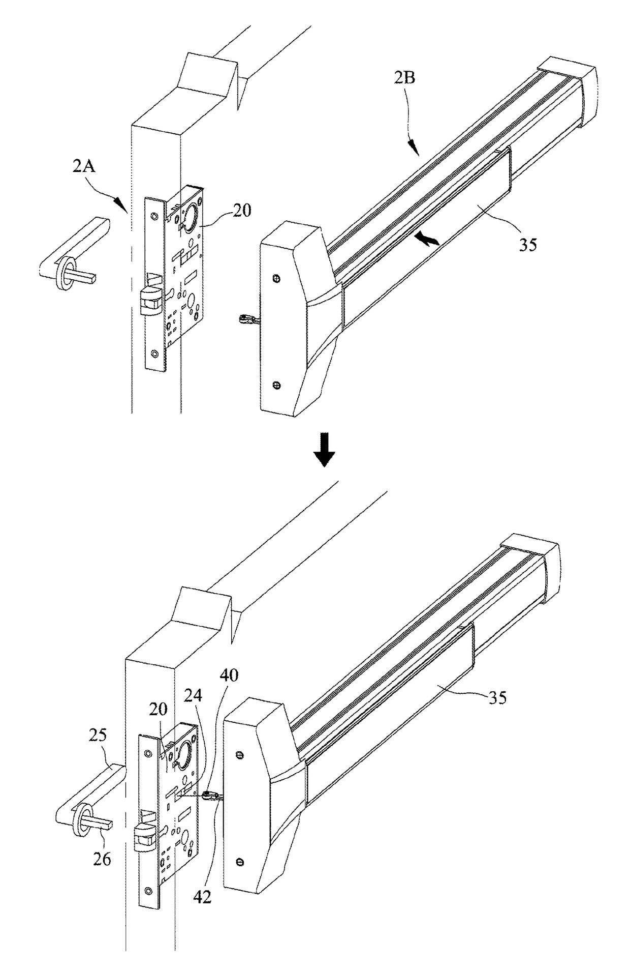
[0025]FIG. 4 is a schematic diagram of a fire door mounted with a fire door lock according to a preferred embodiment of the present invention. The lock comprises a first opening unit 2A and a second opening unit 2B, and in particular features an improvement on the transmission components of the pressing handle 35 of the second opening unit 2B mounted on a fire door. The first opening unit 2A is disposed between door panels inside the fire door for activating a locking bolt 21 to extend from and retract into the first opening unit 2A in a horizontal direction so as to engage or disengage the lock.

[0026]Please refer to FIGS. 5 and 6, which illustrate the first opening unit 2A and the second opening unit 2B, respectively.

[0027]As shown in FIG. 5, the first opening unit 2A comprises: a lock housing 20 for accommodating the transmission components of the locking bolt 21; a locking bolt base 22 having a protruding part 22a; and a rotation device 23 connected to an external rotatable handl...


PUM


Abstract

A fire door lock is provides. A first opening unit is installed in a fire door panel to move a door locking bolt. A second opening unit laterally located on the fire door has a pressing handle coupled with an actuating block for operating the locking bolt. When the pressing handle is pushed and pressed, the actuating block activates an actuating rod and a linking arm to move horizontally. One end of the linking arm is coupled to a driving lever which is induced by the linking arm to swing. One end of the driving lever has a pulley extending into the first opening unit to activate a locking bolt base connected to the locking bolt to move horizontally. The locking bolt is accordingly adapted to extend from or retract into the first opening unit in a horizontal direction to facilitate the release or engagement of the lock.

Description

BACKGROUND OF THE PRESENT INVENTION[0001]1. Field of the present invention[0002]The present invention relates to fire door locks, and, more particularly, to a fire door lock which allows a user to easily push forward to open a fire door mounted with the fire door lock.[0003]2. Description of Related Art[0004]A conventional fire door, as shown in FIG. 1, is opened by pressing a handle 11 of a handle frame base 10 horizontally located in the middle of the fire door, whereby a locking bolt 12d in a lock housing 12 is retracted and relieves a locked state that closes and locks the fire door and the fire door is opened. This operation is achieved by a diagonal depression motion of the handle 11 which is pressed by a user to move in a downward and diagonal direction.[0005]Please refer to FIGS. 2 and 3, which show a conventional fire door lock that is rotated by 90 degrees and oriented in a horizontal direction for clear illustration. The handle frame base 10 houses a pressing handle 11 th...

Claims


Application Information

Patent Timeline
Patent Type & Authority Patents(United States)
IPC IPC(8): E05B65/10E05B63/16
CPCE05B65/104E05B65/1053E05B63/16
Inventor LIN, CHING-TIEN
Owner THASE ENTERPRISE CO LTD
Why Eureka
Try Eureka