Connecting terminal and method for fitting a connecting terminal

a technology of connecting terminals and connectors, applied in the direction of connecting devices, electrical equipment, electrical contacts, etc., can solve the problems of increasing wear on the plug-in connection, impairment of electrical contact, etc., and achieve the effects of increasing the high current carrying capacity, and assisting with the mechanical stability of the connecting terminal

Active Publication Date: 2018-07-24
WAGO VERW GMBH
View PDF19 Cites 15 Cited by
  • Summary
  • Abstract
  • Description
  • Claims
  • Application Information

AI Technical Summary

Benefits of technology

[0008]Another advantage of the invention is that the tried and tested construction of known individual terminals of very compact design, such as that illustrated in DE 10 2013 101 409 A1 for example, can be transferred to connecting terminals, in particular dual terminals. Thus, in particular, an embodiment with a lever-actuated opening mechanism accommodated compactly in the housing can now be implemented as a connecting terminal.
[0009]The connecting terminal according to the invention can be designed as an individual connecting terminal, in which only the two conductor insertion openings arranged on opposite housing sides are provided, or as a multiple connecting terminal, e.g. in such a way that a plurality of individual connecting terminals are arranged adjacent to one another in a row. In this case, it is possible, in particular, for there to be an electrical connection, e.g. via a common conductor bar, between adjacent connecting terminals in the row of connecting terminals.
[0010]It should be noted that the connecting terminal is not an electrical plug-in connection. Electrical plug-in connections are of fundamentally different construction from connecting terminals since the electrical plug-in connections are designed for multiple connection and release of the plug connector parts to and from one another, while a connecting terminal, in particular the connecting terminal according to the invention, although being formed by a plurality of parts in modular fashion, is not designed to enable the housing parts to be taken apart or released from one another after said housing parts have been fitted together. Thus, the coupling means for the mechanical coupling of the housing parts can be designed as a latching or snap-in connection, for example, in particular as a connection which cannot be opened again without damage or can be opened again only with a special tool.
[0011]To provide the electrical connection between the spring-force clamping connections of the connecting terminal, a respective conductor bar element can be arranged in the first and in the second housing part, for example. The conductor bar elements can then be connected to one another by means of a plug-in or screwed joint.
[0012]According to an advantageous development of the invention, the connecting terminal has a conductor bar which is continuous from the first spring-force clamping connection to the second spring-force clamping connection. In particular, the conductor bar can be produced integrally from a metallic material. This has the advantage that the electrical connection between the conductors to be connected to one another by the connecting terminal is optimized and a high current carrying capacity can be achieved. Moreover, the continuous conductor bar assists with the mechanical stability of the connecting terminal.
[0013]According to an advantageous development of the invention, the first housing part is coupled mechanically to the second housing part via a connecting part arranged in the region of transition from the first to the second housing part and formed as a separate component. In this way an additional component is introduced, which is used for mechanically coupling the housing parts of the connecting terminal and can additionally exert a supporting effect, which thus increases the stability of the connecting terminal. In this case, the connecting part can be designed in the manner of a central piece or of a support component, for example. As will be explained below, the connecting part can be designed as a multifunctional component with additional functions.

Problems solved by technology

Accordingly, the electrical plug-in connection is also subject to mechanical stresses during the operation of the connecting terminal, which can lead to increased wear on the plug-in connection and accordingly to an impairment of the electrical contact.

Method used


Image

  • Connecting terminal and method for fitting a connecting terminal
  • Connecting terminal and method for fitting a connecting terminal
  • Connecting terminal and method for fitting a connecting terminal

Examples


Embodiment Construction

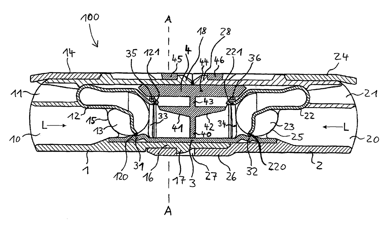
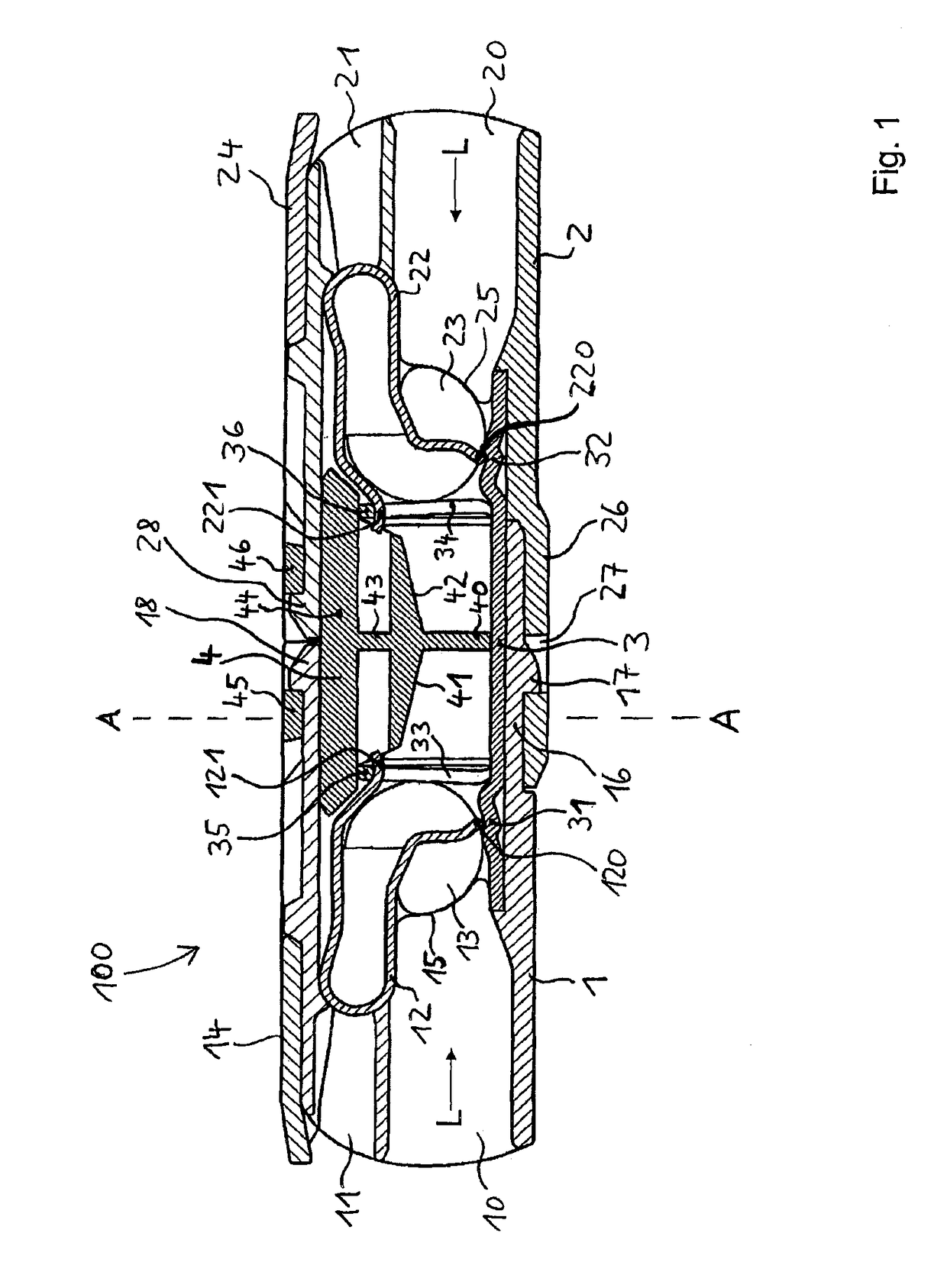
[0060]The connecting terminal shown in FIG. 1 has a first housing part 1 and a second housing part 2. The housing parts 1, 2 have a parting plane arranged vertically in FIG. 1 and are disposed in a “back-to-back” arrangement. Only in the lower region do the housing parts 1, 2 overlap by means of respective housing regions 16, 26. Otherwise, the housing parts 1, 2 are of substantially identical mirror-symmetrical construction internally. Each of the housing parts 1, 2 has a conductor insertion opening 10, 20, a test opening 11, 21, a clamping spring 12, 22 arranged in the housing part 1, 2, and a lever-actuated opening mechanism having an actuating lever 13, 14 and 23, 24, respectively, which is provided for opening a clamping point of respective spring-force clamping connections.

[0061]A conductor bar 3, which is manufactured from electrically conductive metallic material, is furthermore arranged in the interior of the housing parts 1, 2. As can be seen in FIG. 1, the conductor bar 3...


PUM


Abstract

A connecting terminal for connecting at least two electrical conductors to one another, wherein the connecting terminal has at least two separate housing parts which are mechanically connected to one another and each have a conductor insertion opening for at least one electrical conductor which is to be connected on opposite housing sides, wherein there is a first spring-force clamping connection for making electrical contact with a first electrical conductor in a first housing part of the at least two separate housing parts, and there is a second spring-force clamping connection for making electrical contact with the second electrical conductor in the second housing part of the at least two separate housing parts. A method for fitting a connecting terminal for connecting at least two electrical conductors is also provided.

Description

[0001]This nonprovisional application is a continuation of International Application No. PCT / EP2015 / 080310, which was filed on Dec. 17, 2015, and which claims priority to German Patent Application No. 10 2014 119 421.7, which was filed in Germany on Dec. 22, 2014, and which are both herein incorporated by reference.BACKGROUND OF THE INVENTIONField of the Invention[0002]The invention relates to a connecting terminal for connecting at least two electrical conductors to one another, wherein the connecting terminal has at least two separate housing parts, which are connected mechanically to one another and, on opposite housing sides, each have a conductor insertion opening for at least one electrical conductor which is to be connected, wherein there is a first spring-force clamping connection for making electrical contact with a first electrical conductor in a first housing part of the at least two separate housing parts, and there is a second spring-force clamping connection for making...

Claims


Application Information

Patent Timeline
Patent Type & Authority Patents(United States)
IPC IPC(8): H01R12/88H01R4/28H01R4/52H01R4/48
CPCH01R4/28H01R4/4836H01R4/52H01R12/88H01R4/4845H01R13/506H01R13/508H01R4/48455H01R4/48365
Inventor KOELLMANN, HANS-JOSEF
Owner WAGO VERW GMBH
Why Eureka
Try Eureka