Low-profile loudspeaker

a low-profile, loudspeaker technology, applied in the field of diaphragms and loudspeakers, can solve the problems of simple flat shallow diaphragms, simple cone shapes that are not practical, and can not be easily retracted, so as to achieve the effect of reducing the overall depth

Active Publication Date: 2018-07-24
GP ACCOUSTICS (UK) LIMITED
View PDF24 Cites 6 Cited by
  • Summary
  • Abstract
  • Description
  • Claims
  • Application Information

AI Technical Summary

Benefits of technology

[0009]Thus, it is an aim of the present invention to provide a loudspeaker which can be arranged to minimise its overall depth without incurring certain problems that arise from other known solutions to this this aim.

Problems solved by technology

Such resonances are generally undesirable, as they involve movements of the diaphragm that do not correspond to the electrical signal that is being applied via the voice coil.
Where a loudspeaker is designed with a view to minimising its overall depth, such as where the available depth is at a premium, a simple cone shape may be impractical as it lends a significant depth to the loudspeaker.
It is also a challenge that a simple flat shallow diaphragm may suffer from “rocking” movements, i.e. rotational oscillations about an axis perpendicular to the loudspeaker axis.
Rocking vibrations may become problematic if the suspension of the loudspeaker is arranged in a plane that is close to the plane of the surround, as the combined moment that can be exerted by the two restoring forces to counteract a rocking movement is small.
A rocking movement can cause the voice coil to become misaligned within the magnet arrangement and may cause contact between them, leading to damage to the voice coil.

Method used


Image

  • Low-profile loudspeaker
  • Low-profile loudspeaker
  • Low-profile loudspeaker

Examples


Embodiment Construction

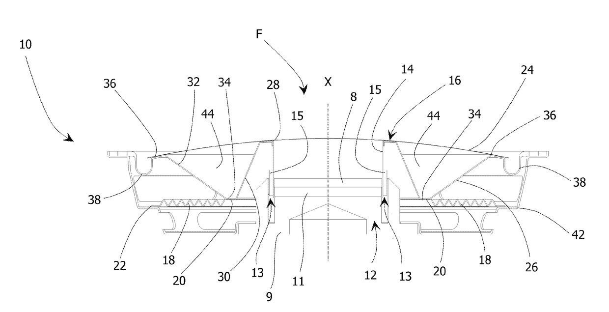
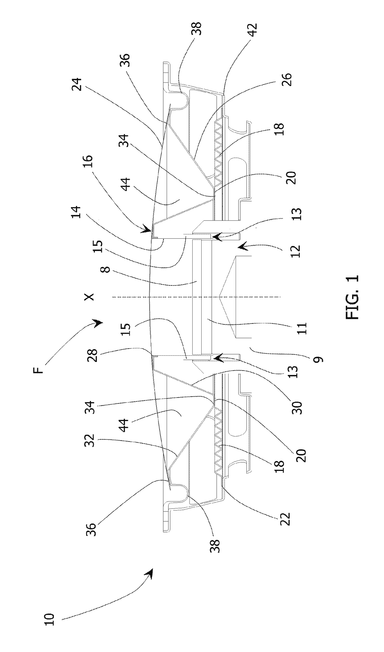
[0027]FIG. 1 shows a loudspeaker 10 embodying the present invention. This has a magnet structure 12, of a conventional format. A permanent magnet 11 is held within a pair of pole pieces 8, 9 which are shaped to direct the magnetic flux and create a strong localised magnetic field across a short annular gap 13 between opposing faces of the pole pieces 8. 9. A cylindrical voice coil former 14 lies within the magnetic field established in the gap 13 by the magnet structure 12, and carries a voice coil 15 which is then responsive to electrical signals to undergo excursions from a rest position along an axis of motion X. A driven body 16 is connected to the voice coil 14 and is moveable to project acoustic waves from a front F of the loudspeaker 10. A suspension 18 provides a restoring for to the driven body 16 towards the rest position, the suspension 18 extending from an attachment point 20 on the driven body 16 to an attachment point 22 on a fixed portion of the loudspeaker 10.

[0028]T...


PUM


Abstract

The present invention relates to a loudspeaker which can be arranged to minimise its overall depth while also increasing the breakup frequency and reducing potential rocking vibrations. Accordingly, the present invention is directed to a loudspeaker, comprising a magnet structure, and a voice coil lying within a magnetic field established by the magnet structure and responsive to electrical signals to undergo excursions from a rest position along an axis of motion; a driven body, connected to the voice coil and moveable to project acoustic waves from a front of the loudspeaker; and a suspension for providing a restoring force to the driven body towards the rest position, the suspension extending from an attachment point on the driven body to an attachment point on a fixed portion of the loudspeaker; wherein the driven body comprises a diaphragm and a support structure extending rearwardly from a connection point with the voice coil to a connection point with the suspension located rearward of the frontal part of the magnet structure.

Description

CROSS REFERENCE TO RELATED APPLICATION[0001]This application claims priority to and benefits of GB Patent Application No. 1516479.1, filed Sep. 17, 2015, the content of which is hereby incorporated by reference in its entirety.FIELD OF THE INVENTION[0002]The present invention relates to the field of loudspeakers, and especially relates to diaphragms and to loudspeakers having diaphragms.BACKGROUND ART[0003]A loudspeaker typically has a voice coil comprising a conductor through which a current may be passed, placed within a magnet assembly so that when current is passed through the voice coil an electromagnetic driving force is produced. This in turn drives a driven body, such as a diaphragm. Conventionally, this vibrates along the loudspeaker axis (i.e. the axis which passes from a front to a rear of the loudspeaker and which is substantially central to the loudspeaker, around which the loudspeaker is usually substantially rotationally symmetric), driven by a driver mechanism such a...

Claims


Application Information

Patent Timeline
Patent Type & Authority Patents(United States)
IPC IPC(8): H04R9/00H04R7/02H04R9/06H04R9/04H04R7/14
CPCH04R9/04H04R7/02H04R9/06H04R9/043H04R2207/021H04R7/14H04R9/02H04R2400/11
Inventor PERKINS, GEORGE
Owner GP ACCOUSTICS (UK) LIMITED
Why Eureka
Try Eureka