Connector having a shorting terminal with a pair of press-fit projections

a shorting terminal and projection technology, applied in the field of connectors, can solve the problems of difficult to bring the jig into contact with the end part, the end part of the rising portion on the base plate side is difficult to deform, and the late entering projection may not be able to sufficiently suppress rattling, etc., to achieve the effect of preventing excessive deflection of the resilient contact piece, reducing the size and simplifying the shape of the shorting terminal

Active Publication Date: 2018-08-14
SUMITOMO WIRING SYST LTD
View PDF23 Cites 0 Cited by
  • Summary
  • Abstract
  • Description
  • Claims
  • Application Information

AI Technical Summary

Benefits of technology

[0007]According to the present invention, even if the press-fit groove is pushed and widened by the press-fit projection first entering the press-fit groove, the formation of a clearance between the later entering press-fit projection and the press-fit groove can be prevented. Thus, both of the press-fit projections entering one press-fit groove can reliably suppress rattling.
[0008]The press-fit projection located on the rear side in the press-fitting direction may be arranged near a contact portion of the resilient contact piece configured to contact the terminal fittings. According to this configuration, since rattling can be prevented reliably near the contact portion of the resilient contact piece by increasing the height of the press-fit projection located on the rear side in the press-fitting direction, the rattling of the shorting terminal can be suppressed effectively.
[0009]The shorting terminal may include a base plate in the form of a flat plate having the press-fit projections, and a rising portion rising in a direction intersecting with the press-fitting direction from a rear end of the base plate in the press-fitting direction. The rising portion may be inclined so that a rising end is located more forward than a base plate side in the press-fitting direction. According to this configuration, the shorting terminal can be accommodated into the housing by pressing the end part of the rising portion on the base plate side with a jig. The end part of the rising portion on the base plate side is difficult to deform even if pressed by the jig. Thus, the push-in amount of the shorting terminal can be controlled easily. In addition, a pressing force of the jig efficiently acts on the base plate. Therefore, the press-fit projections provided on the base plate can be press-fit efficiently. Further, there is conventionally known a shorting terminal in which a box to be pressed by a jig is provided to surround a resilient contact piece. However, material cost can be reduced since the shorting terminal of the invention does not need a box.
[0011]The rising portion may be at a side of the resilient contact piece opposite to a side to be brought into contact with the terminal fittings and may prevent excessive deflection of the resilient contact piece. According to this configuration, the rising portion has an excessive deflection prevention function. Thus, the shape of the shorting terminal can be simplified as compared to the case where an excessive deflection preventing portion is provided separately provided in the shorting terminal.
[0012]The shorting terminal may include a projecting piece projecting on the base plate and to be inserted into the press-fit groove. A front edge in the press-fitting direction, out of a peripheral edge of the projecting piece contacts a back end of the press-fit groove to position the shorting terminal. Thus, the front edge of the projecting piece is inclined so that an end on a projecting end side is located more forward than an end on the base plate side in the press-fitting direction. According to this configuration, the front edge of the projecting piece contacts the back end of the press-fit groove to position the shorting terminal. Thus, the shorting terminal can be positioned accurately since a point of contact is clear, for example, as compared to the case where the entire front edge of the projecting piece comes into contact with the back end of the press-fit groove.

Problems solved by technology

At that time, if a pair of projections are provided on front and rear sides, the groove is pushed and widened by the projection first entering the groove of the housing and the later entering projection may not be able to sufficiently suppress rattling due to a clearance formed between the groove and this projection or the like.
The end part of the rising portion on the base plate side is difficult to deform even if pressed by the jig.
I If no recess is formed on the rear end part of the shorting terminal accommodation chamber in the press-fitting direction, a tip part of the jig easily contacts a wall surface of the shorting terminal accommodation chamber and it could be difficult to bring the jig into contact with the end part of the rising portion on the base plate side.

Method used


Image

  • Connector having a shorting terminal with a pair of press-fit projections
  • Connector having a shorting terminal with a pair of press-fit projections
  • Connector having a shorting terminal with a pair of press-fit projections

Examples


first embodiment

[0031]A first specific embodiment of the present invention is described in detail with reference to FIGS. 1 to 12.

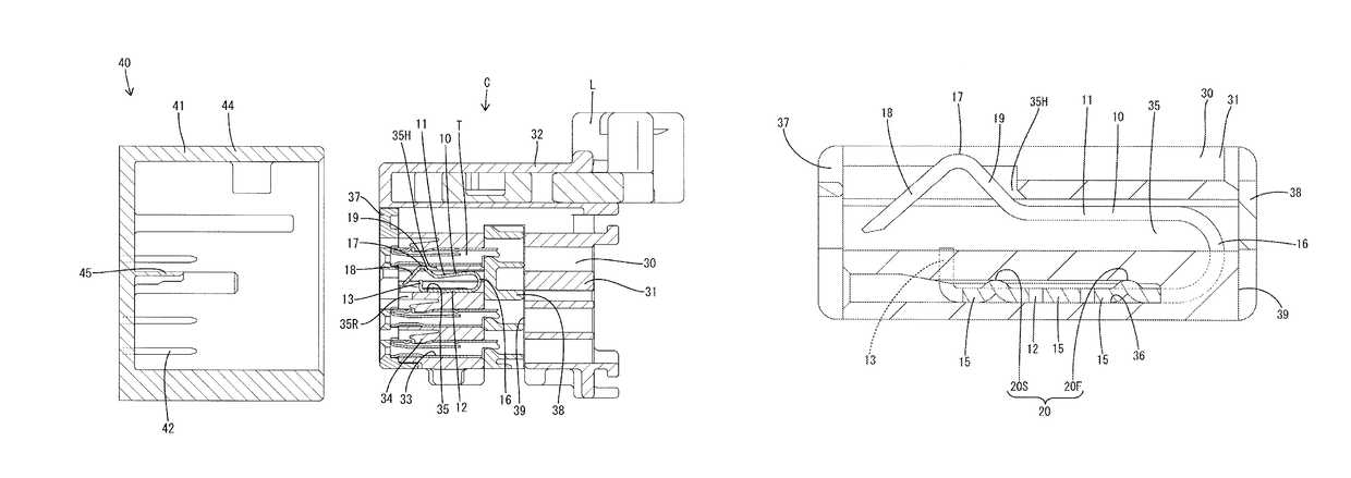
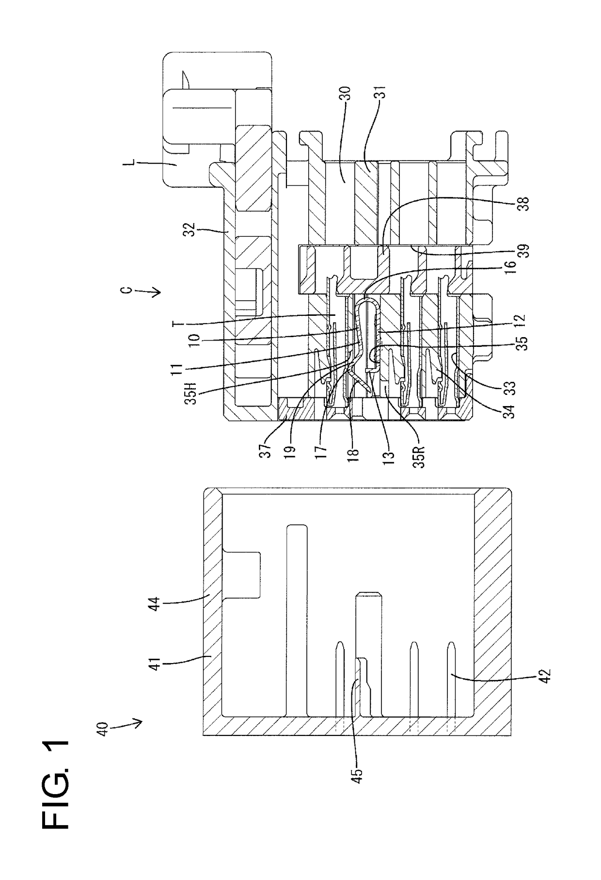
[0032]A connector C in the first embodiment is connected to an ECU for an airbag or the like by being connected to a mating connector 40. In the following description, in each constituent member, connection surface sides of the both connectors C, 40 are respectively referred to as front sides and upper and lower sides of FIG. 1 are referred to as front and rear sides.

[0033]The mating connector 40 includes a housing (hereinafter, referred to as a mating housing 41) made of synthetic resin, and a plurality of male terminal fittings (hereinafter, referred to as mating terminal fittings 42). The mating housing 41 includes a receptacle 44 open forward, and the connector C is fit into this receptacle 44. The mating terminal fittings 42 are mounted in the mating housing 41 such that tip parts thereof project toward a connection side. Further, the mating housing 41 is provided w...

second embodiment

[0071]Next, a connector 50 according to a second specific embodiment of the present invention is described in detail with reference to FIGS. 13 to 17.

[0072]The connector 50 of the second embodiment differs from the first embodiment in that a shorting terminal 51 includes a rising portion 52 rising obliquely backward from the front end (rear end in a press-fitting direction) of a base plate 12. Note that the same components as in the first embodiment are denoted by the same reference signs and repeated description is omitted.

[0073]The connector 50 in the second embodiment includes, as in the first embodiment, shorting terminals 51 each for shorting a pair of terminal fittings T, and a housing 53 for accommodating the terminal fittings T and the shorting terminals 51.

[0074]As in the first embodiment, the shorting terminal 51 is provided with pairs of press-fit projections 20F, 20S to be press-fit into press-fit grooves 36 provided in the housing 53, and a height of first press-fit pro...


PUM


Abstract

It is aimed to provide a connector capable of reliably suppressing rattling by both of a pair of press-fit projections entering one press-fit groove. A connector includes a shorting terminal (10) configured to short a pair of terminal fittings (T) by resilient contact pieces (11) resiliently contacting the pair of terminal fittings (T), and a housing (30) configured to accommodate the terminal fittings (T) and the shorting terminal (10). The shorting terminal (10) includes a pair of press-fit projections (20) to be press-fit into one press-fit groove (36) provided in the housing (30) and separated on front and rear sides in a press-fitting direction into the press-fit groove (36). The pair of press-fit projections (20) are formed such that a height of the press-fit projection located on the front side in the press-fitting direction is smaller than that of the press-fit projection located on the rear side.

Description

BACKGROUNDField of the Invention[0001]The present invention relates to a connector.Description of the Related Art[0002]Conventionally, a connector is known which is provided with a shorting terminal for shorting between a pair of terminal fittings by contacting those terminal fittings. This shorting terminal includes a resilient contact piece capable of resiliently contacting the terminal fittings. In a state where a mating connector is not connected, the resilient contact piece contacts corresponding terminal fittings to short between the terminal fittings. When the mating connector is connected, the resilient contact piece is separated from the terminal fittings by a short releasing portion provided in the mating connector to release a shorted state of the terminal fittings.[0003]For example, in a connector described in Japanese Unexamined Patent Publication No. 2004-134259, a shorting terminal is accommodated into a shorting terminal accommodation chamber provided in a housing fr...

Claims


Application Information

Patent Timeline
Patent Type & Authority Patents(United States)
IPC IPC(8): H01R13/703H01R13/64H01R13/639
CPCH01R13/7031H01R13/64H01R13/639H01R13/41H01R13/7032H01R2201/26
Inventor ITO, TOSHIHIRONORO, YUTAKA
Owner SUMITOMO WIRING SYST LTD
Why Eureka
Try Eureka