
Bicycle lighting device

a technology for bicycles and lighting devices, applied in the direction of bicycle equipment, lighting and heating devices, optical signals, etc., can solve the problem of incorrect judgement of the distance between vehicles and bicycles

Active Publication Date: 2018-08-21
GUAN HUNG TECH
View PDF6 Cites 2 Cited by
  • Summary
  • Abstract
  • Description
  • Claims
  • Application Information

AI Technical Summary

Benefits of technology

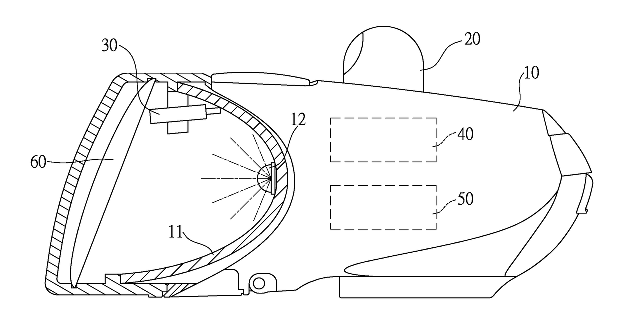
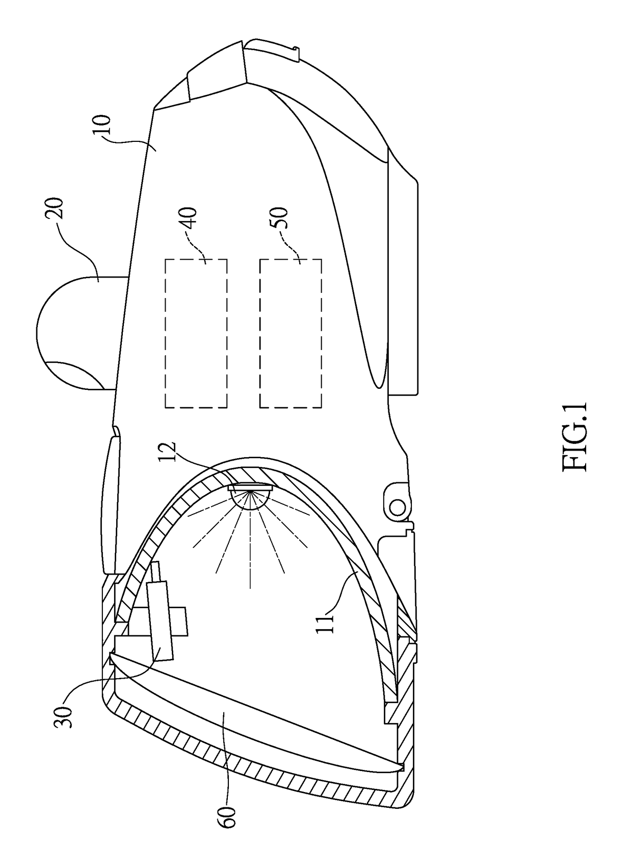
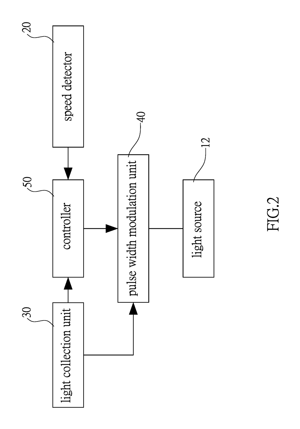
This invention is about a bicycle lighting device that detects the speed of a vehicle approaching it and adjusts the brightness of its headlight to avoid glare. It includes a reflection cup at the front of the device with a light source at the back, a speed detector, a light collection unit, and a pulse width modulation unit. The speed detector detects the speed of the approaching vehicle and sends a signal to a controller. The controller analyzes this data and sends a command to the pulse width modulation unit to adjust the flashing frequency of the light source accordingly. This ensures that the lighting device is always at the optimal brightness for the vehicle's speed. Additionally, the device may have a convex lens to concentrate light beams from the headlight and a photographic semi-conductor to enhance the collection of light. This invention results in improved visibility for bicyclists and reduces the risk of glare from vehicle headlights.

Problems solved by technology

However, if the users to turn on the lighting device, or the lighting device is not operated in a proper mode, such as the bicycle lighting devices may not be seen by vehicles headlights that are much brighter than the bicycle lighting devices.
This may cause incorrect judgement to the distance between the vehicles and the bicycle.

Method used


Image

  • Bicycle lighting device
  • Bicycle lighting device
  • Bicycle lighting device

Examples


Embodiment Construction

[0019]Referring to FIGS. 1 to 7, the bicycle lighting device 10 of the present invention comprises a reflection cup 11 located at the front end of the bicycle lighting device 10. A light source 12 is located at the rear end in the reflection cup 11. A speed detector 20 is connected to the bicycle lighting device 10 and electrically connected to a controller 50. The speed detector 20 detects speed of a vehicle 70 that moves toward the bicycle lighting device 10. A light collection unit 30 is connected to the bicycle lighting device 10 and electrically connected to the controller 50. The light collection unit 30 faces the headlight 71 of the vehicle 70 and collects brightness of the headlight 71 of the vehicle 70 that moves toward the bicycle lighting device 10. A pulse width modulation unit 40 is electrically connected to the light collection unit 30 and the light source 12. When the light collection unit 30 collects brightness of the headlight 71 of the vehicle 70, the output curren...


PUM


Abstract

A bicycle lighting device includes a reflection cup in which a light collection unit and a light source and are respectively located therein. A speed detector is connected to the bicycle lighting device and a controller so as to detecting the speed of a vehicle moving toward the bicycle. The light collection unit collects brightness of the headlight of the vehicle. A pulse width modulation unit is electrically connected to the light collection unit and the light source. The pulse width modulation unit adjusts the flashing frequency of the light source according to the speed of the vehicle moving toward the bicycle lighting device.

Description

BACKGROUND OF THE INVENTION1. Fields of the Invention[0001]The present invention relates to a bicycle lighting device, and more particularly, to a bicycle lighting device and the flashing frequency of the bicycle lighting device changes according to the speed that the vehicle moves toward the bicycle.2. Descriptions of Related Art[0002]The conventional bicycle light devices are usually controlled by the users and provide an ON / OFF switch to control the bicycle light devices to perform in different modes such as full-lighting mode, half-lighting mode, flashing mode and off mode. However, if the users to turn on the lighting device, or the lighting device is not operated in a proper mode, such as the bicycle lighting devices may not be seen by vehicles headlights that are much brighter than the bicycle lighting devices.[0003]Some manufacturers develop a bicycle lighting device which has at least one light emitting diode (LED), and the LED flashes by proper electronic components cooper...

Claims


Application Information

Patent Timeline
IPC IPC(8): B62J6/00B60Q1/46B62J6/04F21V33/00B60Q1/30
CPCB62J6/04B60Q1/46B60Q1/30B60Q2300/43B60Q2300/054B60Q1/0023B62J6/26B62J6/16B62J45/412B60Q1/535B60Q1/143B60Q2300/42
Inventor LEE
Owner GUAN HUNG TECH
Learn More