Liquid-charged antivibration device

a technology of anti-vibration and liquid-charged batteries, which is applied in the direction of shock absorbers, jet propulsion mounting, transportation and packaging, etc., can solve the problems of unnecessarily significant extension of damping characteristics, degraded damping characteristics, and inability to achieve desired anti-vibration performance, and achieves effective improvement of stiffness of elastic partitioning members, the effect of reducing the frequency characteristic associated with the change in amplitude and low dynamic spring characteristics

Active Publication Date: 2018-08-21
YAMASHITA RUBBER CO LTD
View PDF5 Cites 0 Cited by
  • Summary
  • Abstract
  • Description
  • Claims
  • Application Information

AI Technical Summary

Benefits of technology

[0009]However, for example, if the characteristics of an orifice passage are set at the time of engine shake and the like, unnecessarily significant damping characteristic is extended at the time of idling or the like. In contrast, if the characteristics of the orifice passage are set at the time of idling or the like, the damping characteristic is degraded at the time of engine shake or the like, and desired antivibration performance can be hardly extended. For this reason, it has been desired to reduce variation in frequency characteristic associated with a variation in amplitude, and thereby reduce amplitude dependency.
[0010]The present invention is made to solve the above problem, and an object of the present invention is to provide a liquid-charged antivibration device for reducing amplitude dependency.
[0012]In this liquid-charged antivibration device, if an input amplitude is relatively small, variation in liquid pressure is absorbed by the thin membrane portion of the elastic partitioning member (i.e., low dynamic spring characteristic is obtained). On the other hand, if the input amplitude is relatively large, the displacement amount of the thick membrane portion of the elastic partitioning member is restricted by the first restricting portion, while the displacement amount of the thin membrane portion is restricted by the second restricting portion, and thus the stiffness of the elastic partitioning member is effectively improved. Thus, change in the frequency characteristic associated with change in the amplitude is reduced, and reduction of amplitude dependency can be achieved.
[0013]Further, the clearance between the thick membrane portion and the first restricting portion is preferably smaller than that between the thin membrane portion and the second restricting portion. When the above condition is met, if the input amplitude is relatively large, the displacement amount of the thick membrane portion is restricted by the first restricting portion, and the displacement amount of the thin membrane portion is subsequently restricted by the second restricting portion. For this reason, the pressure in the main liquid chamber quickly rises to achieve high damping characteristics, and the variation in the frequency characteristic associated with the variation in the amplitude is suitably reduced.
[0014]Still further, as the elastic deformation of the elastic partitioning member is gradually restricted by the difference between the clearances, generation of strike sounds (contact sound between the elastic partitioning member and the restricting portions) can be reduced, compared with a case where the elastic deformation of the elastic partitioning member is restricted at a time.
[0015]Still further, the first restricting portion and the second restricting portion are preferably disposed so as to be at least partially perpendicular to each other. When the above condition is met, the displace amount of the elastic partitioning member can be made uniform, and the amplitude dependency can be reduced more effectively.

Problems solved by technology

However, for example, if the characteristics of an orifice passage are set at the time of engine shake and the like, unnecessarily significant damping characteristic is extended at the time of idling or the like.
In contrast, if the characteristics of the orifice passage are set at the time of idling or the like, the damping characteristic is degraded at the time of engine shake or the like, and desired antivibration performance can be hardly extended.

Method used


Image

  • Liquid-charged antivibration device
  • Liquid-charged antivibration device
  • Liquid-charged antivibration device

Examples


Embodiment Construction

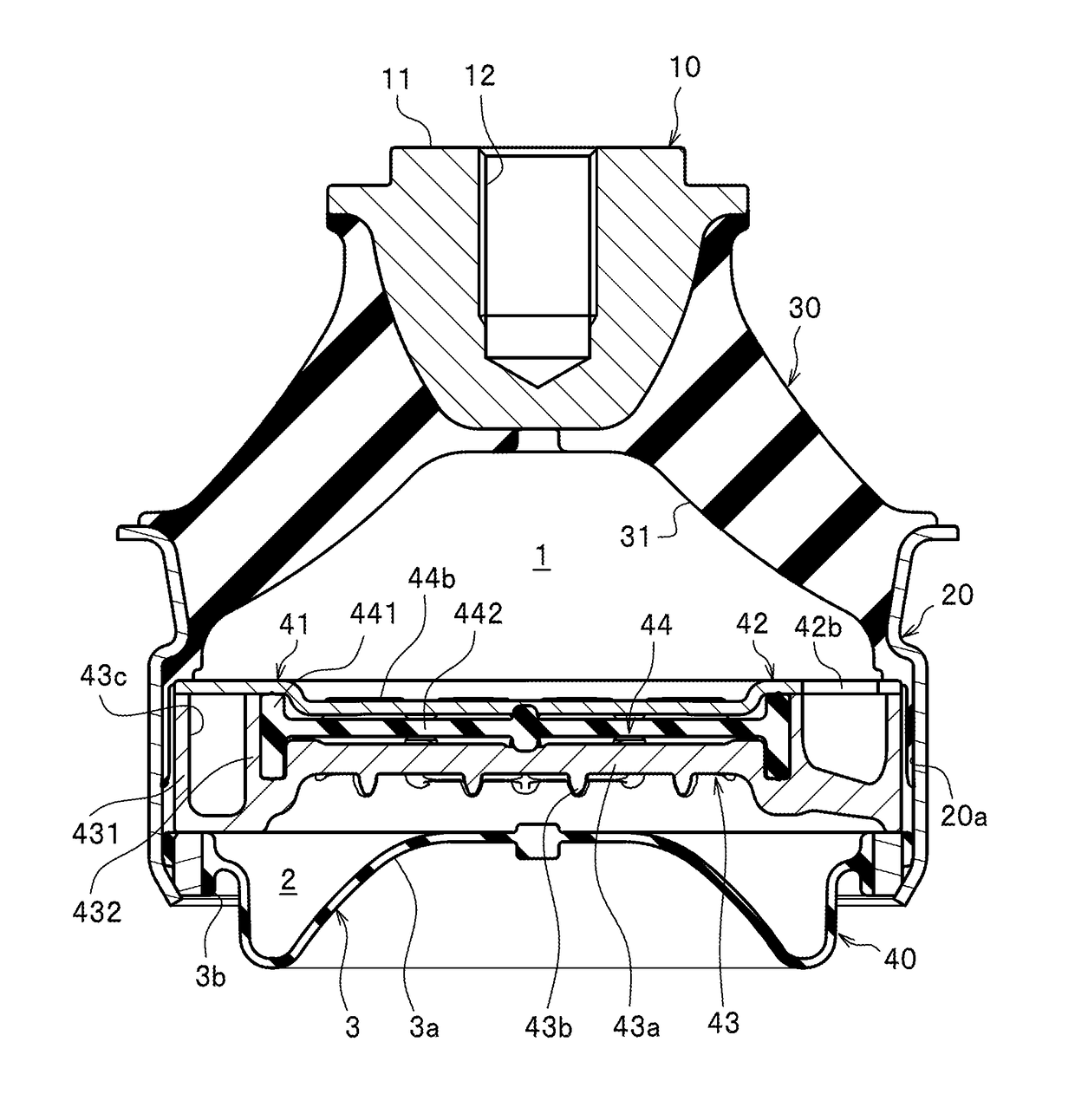
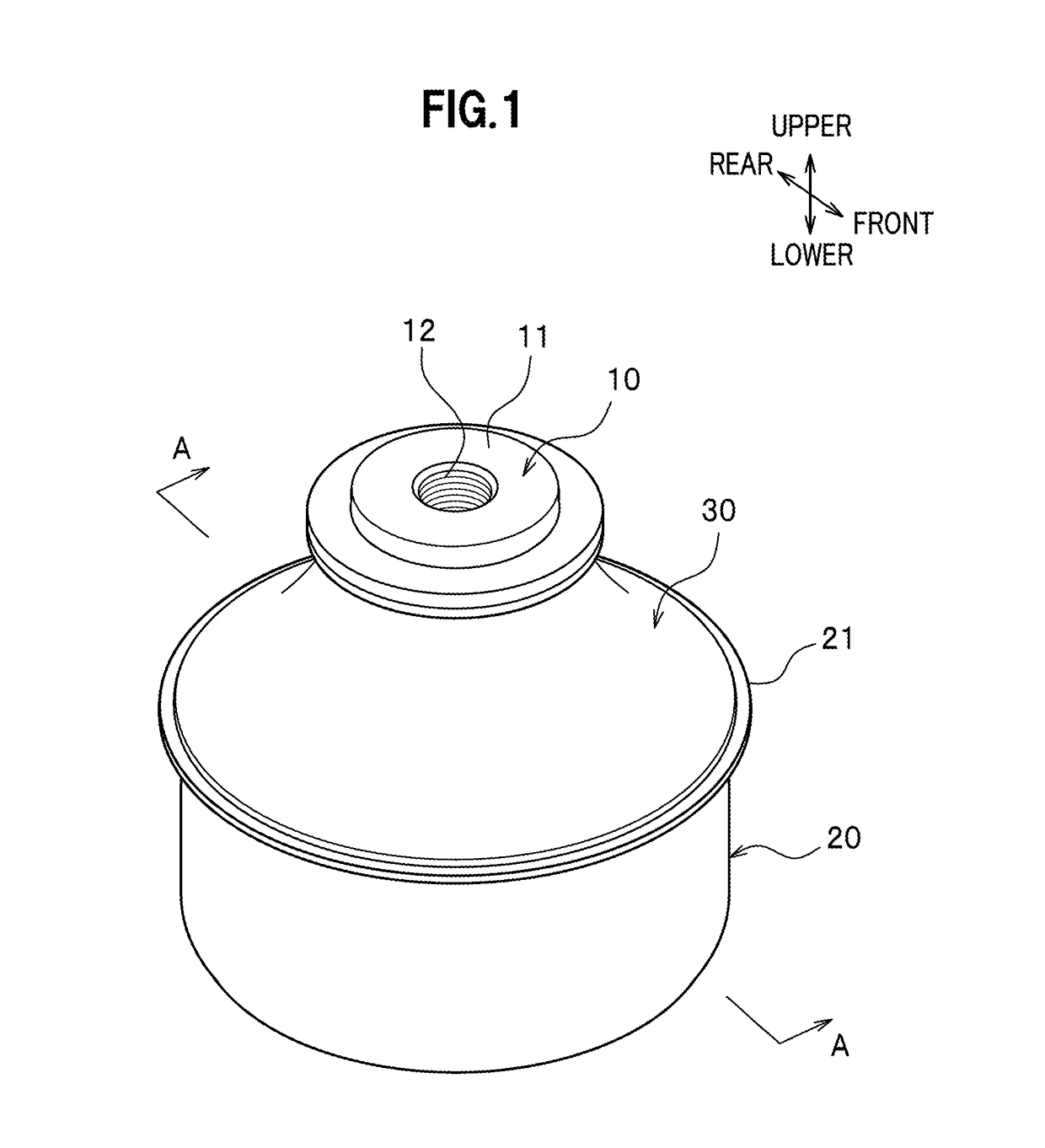
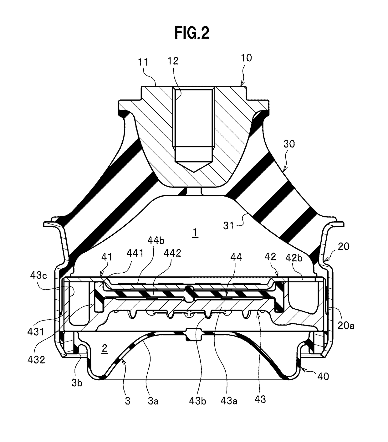
[0024]An embodiment of a liquid-charged antivibration device according to the present invention will be described below, referring to the drawings. In addition, in the following description, the means of wordings “front-rear” and “upper-lower” are based on the direction shown in FIG. 1. However, the wordings “front-rear” and “upper-lower” do not always agree with the front-rear direction and the upper-lower direction of the vehicle body of a vehicle. In addition, the upper-lower direction for the liquid-charged antivibration device is the input direction of primary vibration.

[0025]The liquid-charged antivibration device is an antivibration device of a liquid charging type disposed between a vibration-source side and a non-vibration-source side (vibration receiving side). As shown in FIG. 1, the liquid-charged antivibration device is provided with a first fitting member 10, a second fitting member 20, and an insulator 30 for elastically connecting the first fitting member 10 and the ...


PUM


Abstract

An object of the present invention is to provide a liquid-charged antivibration device for reducing amplitude dependency. Provided is a liquid-charged antivibration device including: a liquid chamber in which operating liquid is charged; and a partitioning member which partitions the liquid chamber into a main liquid chamber and a sub liquid chamber.

Description

CROSS REFERENCE TO RELATED APPLICATION[0001]This application claims the benefit of priority to Japanese Patent Application No. 2015-191502, filed on Sep. 29, 2015, the disclosure of which is hereby incorporated herewith by reference.BACKGROUND OF THE INVENTION[0002]Field of the Invention[0003]The present invention relates to a liquid-charged antivibration device used for an engine mount of a vehicle and the like.[0004]Description of the Related Arts[0005]Conventionally, as this kind of the liquid-charged antivibration device, a device disclosed in Patent Literature 1 (JP 2012-13153 A) is known. This liquid-charged antivibration device includes a first fitting member fitted to an engine, a second fitting member fitted to a vehicle body, and an insulator for connecting the first fitting member and the second fitting member. In this liquid-charged antivibration device, an operating liquid is housed inside the insulator, and the inside of the insulator is partitioned in a main liquid ch...

Claims


Application Information

Patent Timeline
Patent Type & Authority Patents(United States)
IPC IPC(8): F16F13/10B60K5/12
CPCF16F13/105F16F13/10B60K5/1208F16F13/106
Inventor KADOWAKI, HIROKAZUMATSUMOTO, KOICHI
Owner YAMASHITA RUBBER CO LTD
Why Eureka
Try Eureka