
Armature and rotating electrical device

a technology of rotating electrical devices and armatures, which is applied in the direction of rotating magnets, synchronous machines with stationary armatures, windings, etc., can solve problems such as interference with other portions, and achieve the effect of suppressing positional misalignment of terminal portions and suppressing interference of terminal portions

Active Publication Date: 2018-09-04
DENSO CORP
View PDF13 Cites 5 Cited by
  • Summary
  • Abstract
  • Description
  • Claims
  • Application Information

AI Technical Summary

Benefits of technology

The present invention provides an armature that can prevent misalignment of the terminal portion of a crossing wire and reduce interference with other parts. The armature has a retaining section that guides the terminal portion of the wound portion and the terminal portion of the crossing wire, even when they are positioned at different locations on the tooth portion due to the number of turns of the winding. The wound portion is also supported by a base end portion of the retaining projection to prevent shape collapse. Additionally, the crossing wires are designed to pass further inside than the inner radial portions of the plural core configuration members to prevent interference during coupling of the adjacent core configuration members.

Problems solved by technology

When the terminal portion of the wound portion is retained by a snap-fit structure in such cases, the terminal portion of the crossing wire cannot be retained, and the position of the terminal portion of the crossing wire becomes misaligned, causing interference with other portions.

Method used


Image

  • Armature and rotating electrical device
  • Armature and rotating electrical device
  • Armature and rotating electrical device

Examples


Embodiment Construction

[0037]Explanation follows regarding an exemplary embodiment of the present invention, based on the drawings.

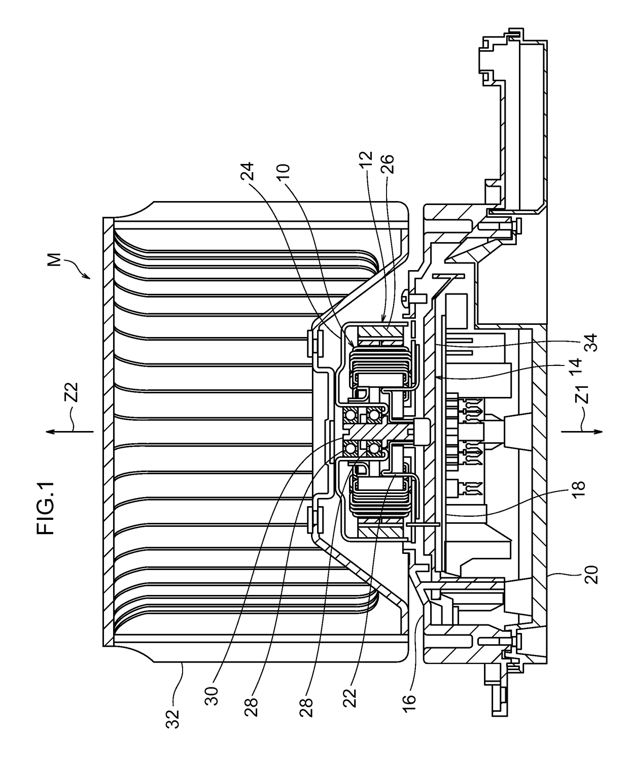
[0038]As illustrated in FIG. 1, a rotating electrical device M according to the present exemplary embodiment includes an armature 10 that is a stator, a rotor 12, a centerpiece 14, a motor holder 16, a circuit board 18, and a case 20.

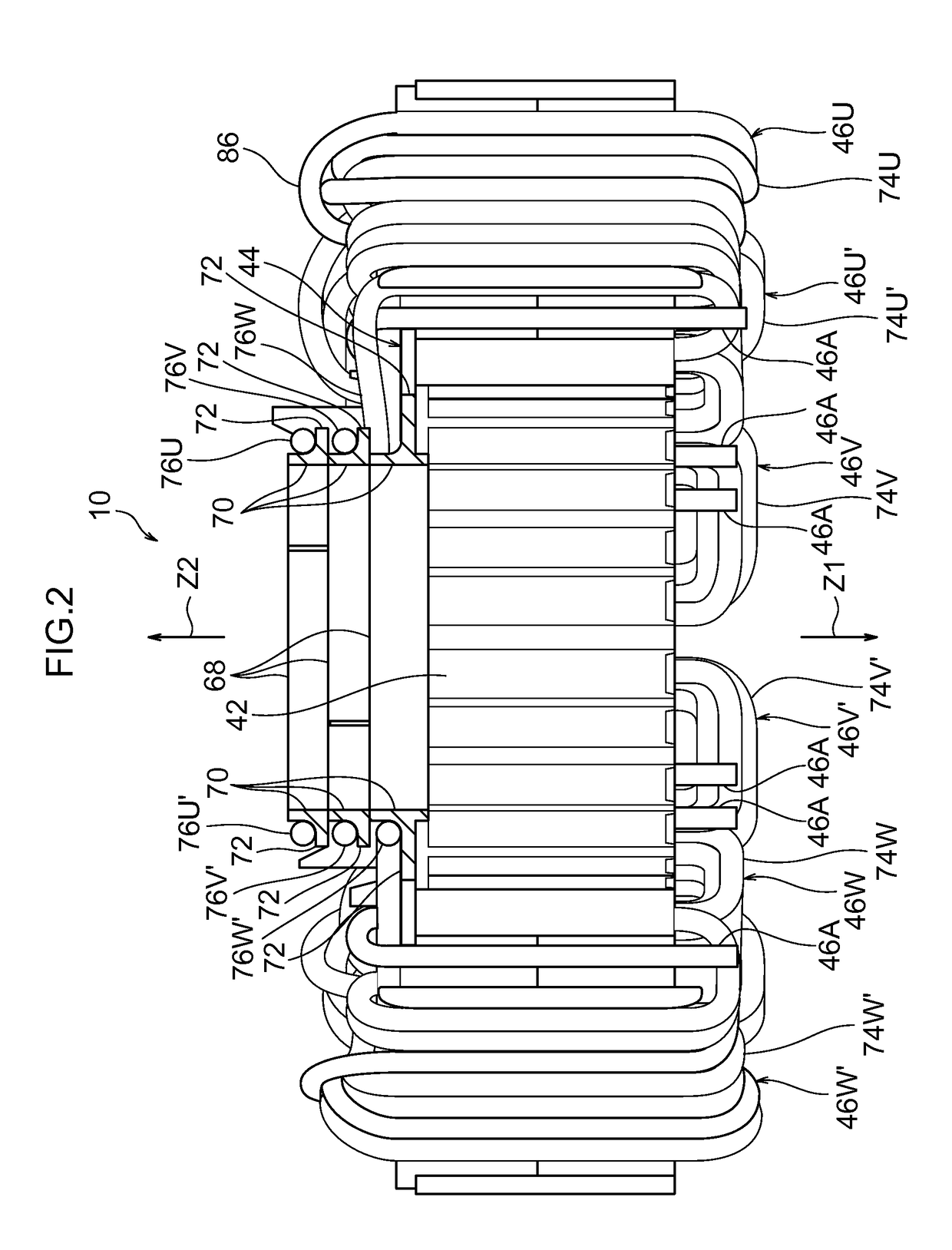
[0039]Specifically, the armature 10 is configured as described below, and is formed in a ring shape. Shaft sections 22 provided at an axial center portion of the centerpiece 14 are press-fitted inside the armature 10, such that the armature 10 is supported by the centerpiece 14.

[0040]The rotor 12 includes a housing 24 with a lidded cylinder shape, and magnets 26 fitted to an inner peripheral face of the housing 24. The magnets 26 are provided at the radial direction outside of the armature 10, facing toward the armature 10. A pair of bearings 28 is provided at the axial center portion of the housing 24, and a rotation shaft 30 is press-fitted insi...


PUM


Abstract

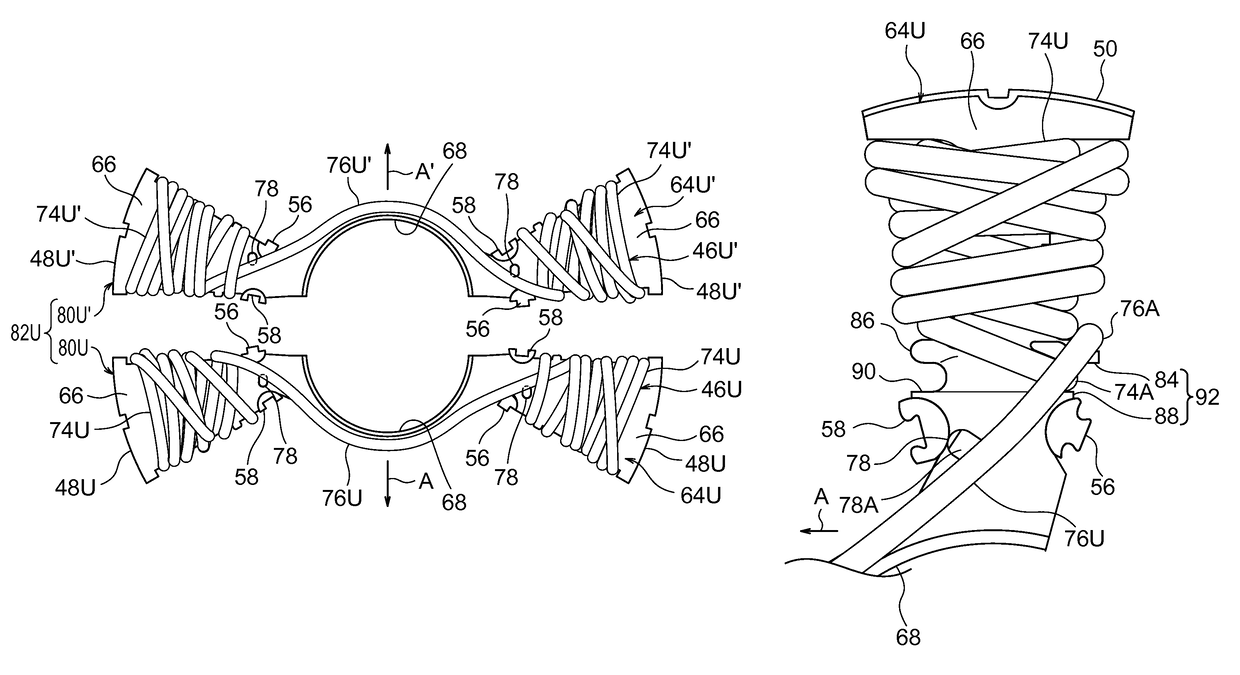
There is provided an armature including: an armature core that includes plural tooth portions extending in a radial direction and disposed in a row around a circumferential direction; an insulator including plural insulation portions integrated with the armature core; plural windings each including plural wound portions wound on the tooth portions with the insulation portions interposed between the wound portions and the tooth portions, and a crossing wire connecting the plural wound portions together; wherein at a tooth portion, a terminal portion of a wound portion and a terminal portion of a crossing wire are positioned at side portions of the tooth portion on the same side as each other in the circumferential direction; and the insulator is provided with a retaining section that retains the terminal portion of the wound portion and guides the terminal portion of the crossing wire.

Description

CROSS-REFERENCE TO RELATED APPLICATION[0001]This application claims priority under 35 USC 119 from Japanese Patent Application No. 2013-240159 filed on Nov. 20, 2013, and Japanese Patent Application No. 2014-179362 filed on Sep. 3, 2014, the disclosures of which are incorporated by reference herein.BACKGROUND[0002]Technical Field[0003]The present invention relates to an armature and a rotating electrical device.[0004]Related Art[0005]The following are known as conventional armatures employing a divided core (see, for example, Japanese Patent Application No. 2012-095871). An armature described in Japanese Patent Application No. 2012-095871 employs an armature core divided into plural core configuration members as a divided core. Plural insulators are employed in the armature, and each of the plural insulators includes plural insulation portions that are attached to the core configuration members, and a coupling portion that couples the plural insulation portions. The armature is prov...

Claims


Application Information

Patent Timeline
Patent Type & Authority Patents(United States)
IPC IPC(8): H02K3/28H02K1/14H02K3/18H02K3/50H02K3/52H02K3/38H02K21/22
CPCH02K1/148H02K3/522H02K21/22H02K2203/12H02K3/38H02K3/50H02K2203/06H02K3/28
Inventor KAGEME, SHIGEAKI
Owner DENSO CORP
Learn More