
Fuel cell comprising a knock pin

a knock pin and fuel cell technology, applied in the direction of fuel cells, fuel cell details, solid electrolyte fuel cells, etc., can solve the problems of damage or the like in the knock pins b>4, and achieve the effect of suppressing positional changes, and increasing the diameter of the insertion hol

Active Publication Date: 2016-11-22
HONDA MOTOR CO LTD
View PDF35 Cites 0 Cited by
  • Summary
  • Abstract
  • Description
  • Claims
  • Application Information

AI Technical Summary

Benefits of technology

[0010]The present invention has been made to solve such problems, and an object of the present invention is to provide a fuel cell stack having simple structure in which it is possible to suppress application of excessive stress to a knock pin.
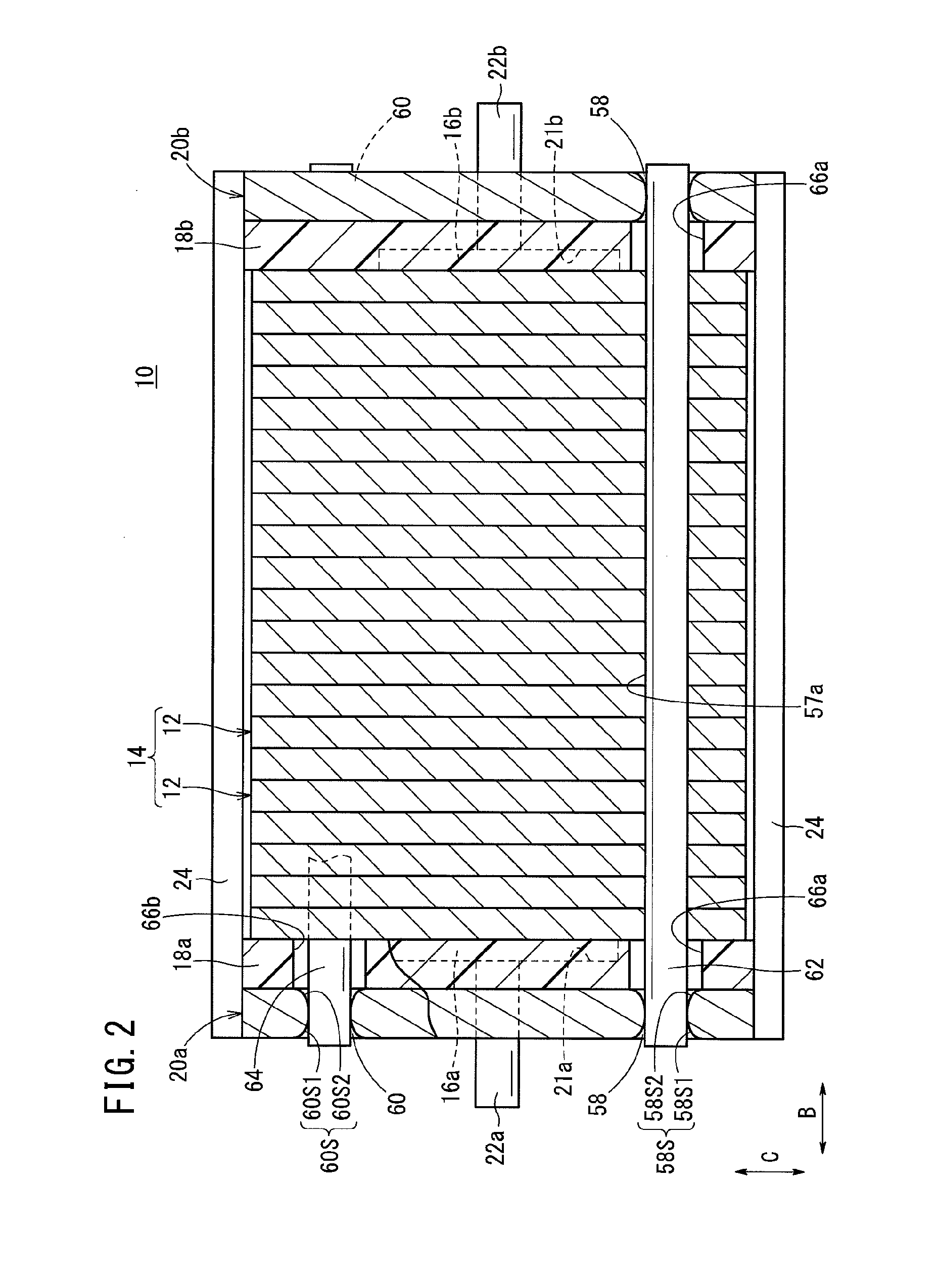
[0012]In this fuel cell stack, a knock pin extending in the stacking direction is provided between the end plates for positioning the stack body. The end plate has an insertion hole for insertion of the knock pin, and a diameter-increasing surface is formed in an inner circumferential surface of the insertion hole in a radial direction spaced from the knock pin to increase the diameter of the insertion hole.
[0013]In the present invention, the knock pin is inserted into the insertion hole of the end plate. Further, the diameter-increasing surface is formed in the inner circumferential surface of the insertion hole in the radial direction spaced from the knock pin to increase the diameter of the insertion hole. In the structure, when an external load is applied to the fuel cell stack in a direction intersecting with the stacking direction of the power generation cells, the knock pin can suppress positional displacement among the power generation cells, and the knock pin can be tilt along the diameter-increasing surface within of the insertion hole. Thus, with the simple structure, it is possible to suppress the excessive stress from being applied locally to a certain portion of the knock pin in a concentrated manner, and it becomes possible to suppress damages or the like of the knock pin as much as possible.

Problems solved by technology

Consequently, damages or the like may occur in the knock pins 4 undesirably.

Method used


Image

  • Fuel cell comprising a knock pin
  • Fuel cell comprising a knock pin
  • Fuel cell comprising a knock pin

Examples


first embodiment

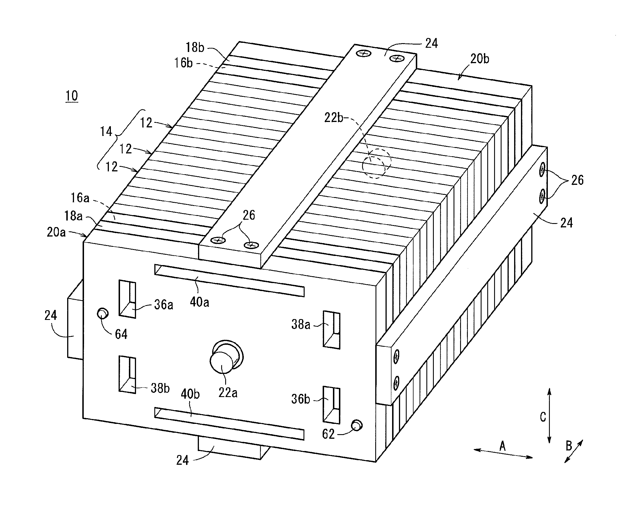
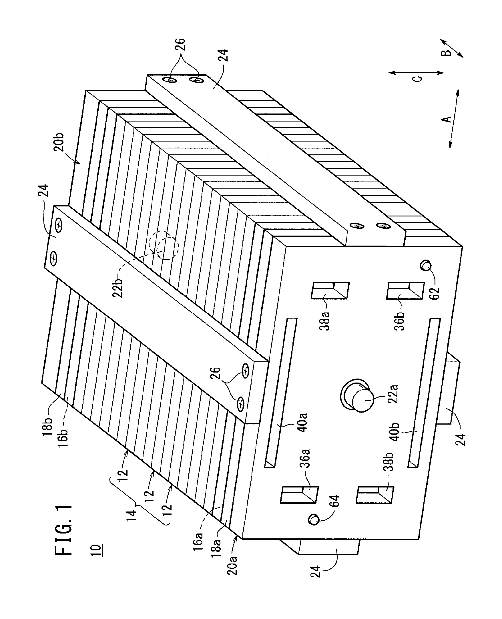
[0025]As shown in FIG. 1, a fuel cell 10 according to the present invention includes a stack body 14 formed by stacking a plurality of power generation cells (fuel cells) 12 in an upright position together in a horizontal direction indicated by an arrow B.

[0026]As shown in FIGS. 1 and 2, at one end of the stack body 14 in a stacking direction, a terminal plate 16a is provided. An insulating plate 18a is provided outside the terminal plate 16a. Further, a first end plate 20a is provided outside the insulating plate 18a. At the other end of the stack body 14 in the stacking direction, a terminal plate 16b is provided. An insulating plate 18b is provided outside the terminal plate 16b. Further, a second end plate 20b is provided outside the insulating plate 18b. The surface sizes of the terminal plates 16a, 16b are smaller than the surface sizes of the insulating plates 18a, 18b, and the terminal plates 16a, 16b are placed inside openings 21a, 21b formed at central portions of the insu...

third embodiment

[0061]FIG. 7 is a cross sectional side view showing a fuel cell stack 90 according to the present invention.

[0062]The fuel cell stack 90 includes a first end plate 92a and a second end plate 92b provided at both ends in the stacking direction. Instead of the insertion holes 58, 60, insertion holes 94, 96 are formed in the first end plate 92a and the second end plate 92b.

[0063]Diameter-increasing surfaces are formed in an inner circumferential surface 94S of the insertion hole 94 in a direction spaced from the knock pin 62 to increase the diameter of the insertion hole 94. Specifically, at both ends of the inner circumferential surface 94S in the axial direction, surfaces 94S1, 94S2 inclined in cross-section are formed as the diameter-increasing surfaces, and the inclined surfaces 94S1, 94S2 are connected together by a surface 94S3 which is flat in cross-section and has a width smaller than a thickness of the first end plate 92a and the second end plate 92b. Preferably, the inclined...

fourth embodiment

[0066]FIG. 8 is a cross sectional side view showing a fuel cell stack 100 according to the present invention.

[0067]The fuel cell stack 100 includes a first end plate 102a and a second end plate 102b provided at both ends in the stacking direction. Insertion holes 104, 106 are formed in the first end plate 102a and the second end plate 102b.

[0068]Diameter-increasing surfaces are formed in an inner circumferential surface 104S of the insertion hole 104 in a direction spaced from the knock pin 62 to increase the diameter of the insertion hole 104. Specifically, at one end of the inner circumferential surface 104S of the insertion hole 104 in the axial direction (inner side), a surface 104S1 inclined in cross-section is formed as the diameter-increasing surface. At the other end of the inner circumferential surface 104S of the insertion hole 104 in the axial direction (outer side), a surface 104S2 which is flat in cross-section and has a width smaller than a thickness of the first end ...


PUM

PropertyMeasurementUnit
diameteraaaaaaaaaa
pressureaaaaaaaaaa
bending stressaaaaaaaaaa

Abstract

In a fuel cell stack, knock pins extending in a stacking direction are provided between a first end plate and a second end plate for positioning a stack body. The first end plate and the second end plate have insertion holes for insertion of knock pins. A diameter-increasing surface is formed in an inner circumferential surface of each insertion hole in a direction spaced from the knock pin to increase the diameter of the insertion hole.

Description

CROSS-REFERENCE TO RELATED APPLICATIONS[0001]This application is based upon and claims the benefit of priority from Japanese Patent Applications No. 2012-268424 filed on Dec. 7, 2012 and No. 2013-229345 filed on Nov. 5, 2013, the contents all of which are incorporated herein by reference.BACKGROUND OF THE INVENTION[0002]1. Field of the Invention[0003]The present invention relates to a fuel cell stack including a stack body formed by stacking a plurality of power generation cells in a stacking direction. Each of the power generation cells is formed by stacking a membrane electrode assembly and a separator. The membrane electrode assembly includes a pair of electrodes and an electrolyte membrane interposed between the electrodes. End plates are provided at both ends of the stack body in the stacking direction.[0004]2. Description of the Related Art[0005]For example, a solid polymer electrolyte fuel cell employs a polymer ion exchange membrane as an electrolyte membrane, and the polyme...

Claims


Application Information

Patent Timeline
Patent Type & Authority Patents(United States)
IPC IPC(8): H01M8/02H01M8/24H01M8/10
CPCH01M8/247H01M2008/1095Y02E60/50
Inventor NISHIYAMA, TADASHINARA, YUSUKE
Owner HONDA MOTOR CO LTD
Learn More