
Liquid ejecting head unit and liquid ejecting apparatus

a liquid ejecting head and liquid ejecting technology, which is applied in mechanical devices, engine seals, printing and other directions, can solve the problems of complex assembly, tube to both an upper and lower passage, and inability to eject liquid, etc., and achieve the effect of improving assembility

Active Publication Date: 2014-12-25
SEIKO EPSON CORP
View PDF3 Cites 4 Cited by
  • Summary
  • Abstract
  • Description
  • Claims
  • Application Information

AI Technical Summary

Benefits of technology

The patent text describes a liquid ejecting apparatus that has a sealing mechanism to prevent leakage and apply pressure in the penetration direction. The technical effect of this invention is to improve the assembly and performance of the liquid ejecting apparatus by allowing preferable connections between passages and reducing the impact of pressure on the liquid ejecting head.

Problems solved by technology

As a result, a malfunction may occur, such as separation of the passage member and the liquid ejecting head, separation of a layer member that is a constituent of the liquid ejecting head, or deviation from positions at which the drops of ink are expected to be supplied on an ejected medium, which is caused by warping of the liquid ejecting surface of the liquid ejecting head.
Although the connection of two passages through a tube may reduce pressure in a direction perpendicular to a liquid ejecting surface, it is necessary to fit the tube to both an upper passage and a lower passage and assembling may be complicated.
Besides, in both cases in which the plate-like sealing member is used and the tube-like sealing member is used, it is necessary to press the upstream passage member relatively against the downstream passage member in assembling the upstream passage member and the downstream passage member, and the pressing may cause pressure to be applied in the direction in which the upstream passage member and the downstream passage member are separated from each other.

Method used


Image

  • Liquid ejecting head unit and liquid ejecting apparatus
  • Liquid ejecting head unit and liquid ejecting apparatus
  • Liquid ejecting head unit and liquid ejecting apparatus

Examples


first embodiment

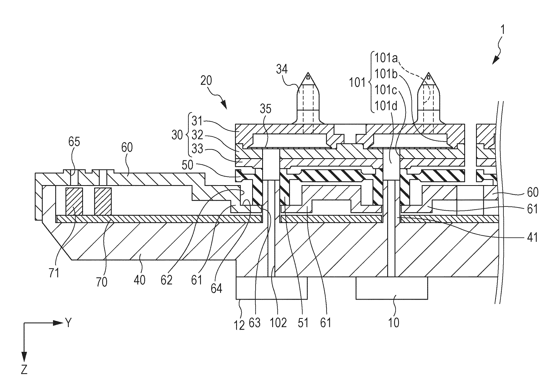
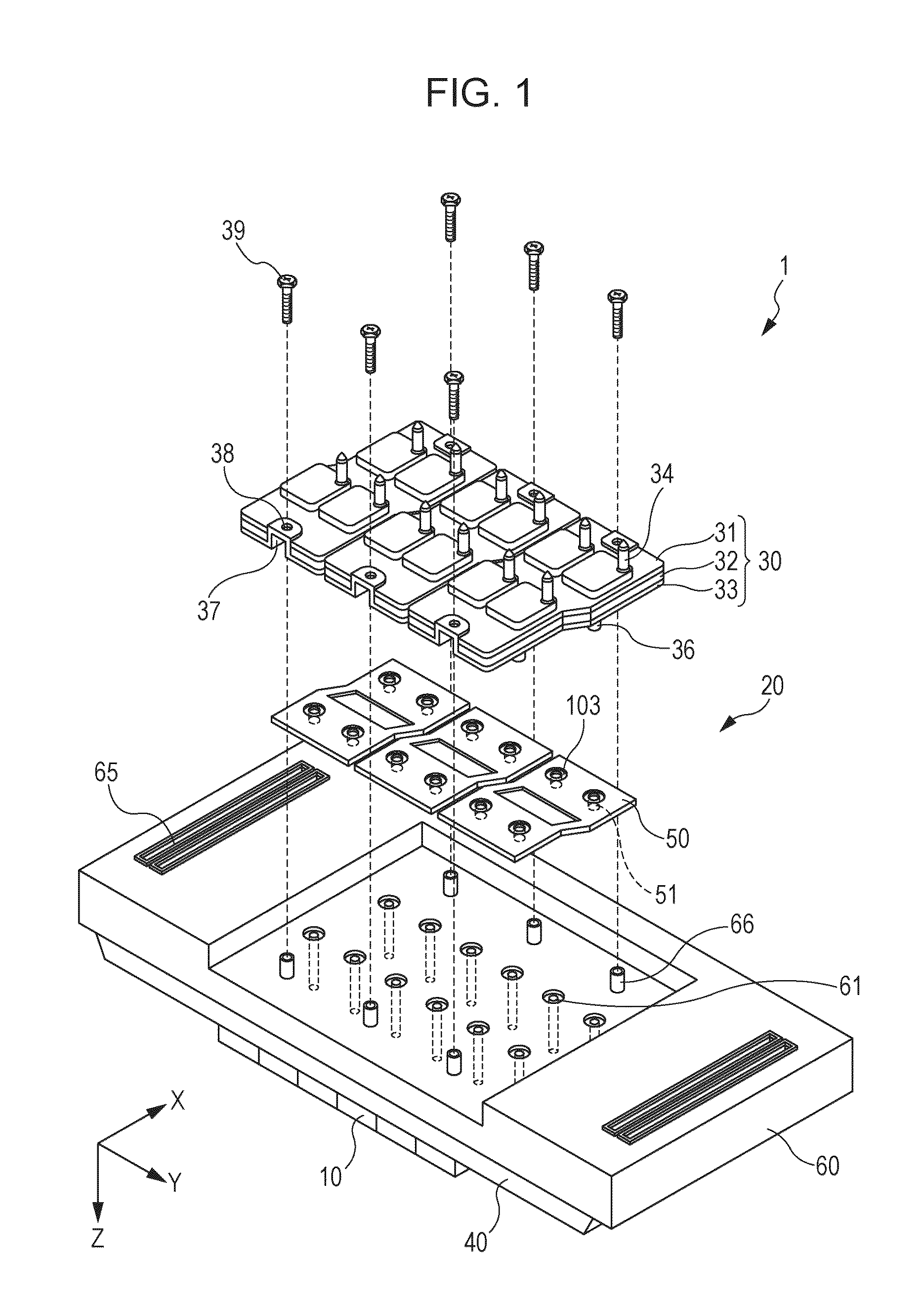
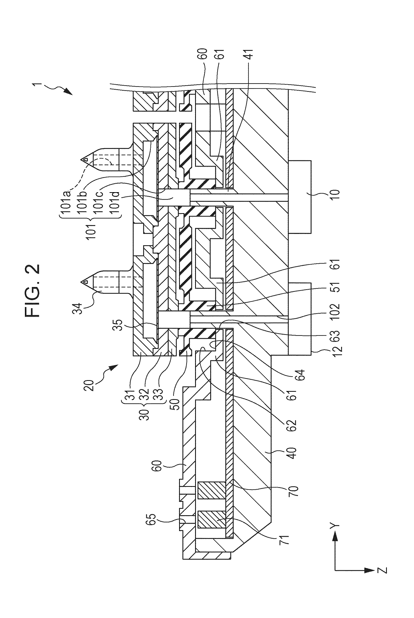
[0021]FIG. 1 is an exploded perspective view of an ink jet recording head unit, which is an example of a liquid ejecting head unit according to a first embodiment of the invention. FIG. 2 is a cross-sectional view of the ink jet recording head unit. FIG. 3 is a cross-sectional view in which a main part of FIG. 2 is enlarged.

[0022]As illustrated, an ink jet recording head unit 1, which is hereinafter also referred to merely as the head unit 1 and is an example of the liquid ejecting head unit according to the present embodiment, includes a plurality of ink jet recording heads 10, which are hereinafter also referred to merely as the recording heads 10 and discharge drops of ink from nozzles, and a passage member 20, which holds the plurality of recording heads 10 and is provided with a liquid passage that supplies liquid to the recording heads 10.

[0023]The recording head 10 includes a liquid ejecting surface 12 on one side, through which the nozzles that discharges drops of ink as liq...


PUM


Abstract

A head unit includes a head, an upstream member with an upstream passage supplied with liquid, a downstream member with a downstream passage communicating with the upstream passage and supplying liquid to the head, an elastic sealer connecting the upstream and downstream passages, and including a tube with a connection passage, and a support between the sealer and the downstream member. In the head unit, the upstream member and the sealer apply pressure in a penetration direction of the connection passage and hermetically seal the upstream passage, the sealer and the downstream member apply pressure in a direction perpendicular to the penetration direction of the tube and hermetically seal the downstream passage, and the support abuts a region on a surface of the sealer, the surface being opposite the upstream member, the region overlapping a region to which the sealer and the upstream member apply pressure.

Description

BACKGROUND[0001]1. Technical Field[0002]The present invention relates to a liquid ejecting head unit that ejects liquid from a nozzle and a liquid ejecting apparatus, and particularly relates to an ink jet recording head unit that discharges ink as liquid and an ink jet recording apparatus.[0003]2. Related Art[0004]Representative examples of a liquid ejecting head unit that ejects liquid include an ink jet recording head unit that discharges drops of ink. For example, JPA-2009-6730 proposes an ink jet recording head unit that includes an ink jet recording head, which discharges drops of ink from a nozzle, and a passage member, which is fixed to the ink jet recording head and supplies ink from a liquid reservoir in which the ink is stored, such as an ink cartridge, to a liquid ejecting head.[0005]The passage member of the ink jet recording head unit includes an upstream passage member, to which the ink is supplied from the liquid reservoir, and a downstream passage member, which hold...

Claims


Application Information

Patent Timeline
IPC IPC(8): B41J2/14
CPCB41J2/1433B41J2/14B41J2002/14362B41J2002/14403B41J2/175F16J15/06
Inventor KANEGAE, TAKAHIRO
Owner SEIKO EPSON CORP
Learn More