
Internal combustion engine

a combustion engine and internal combustion technology, applied in the direction of machines/engines, mechanical equipment, auxilaries, etc., can solve the problems that the negative pressure in the crank chamber cannot be effectively prevented until it blocks the balance hole, etc., and achieves the effect of suppressing the application of excessive negative pressure and high reliability

Active Publication Date: 2013-05-28
SUZUKI MOTOR CORP
View PDF6 Cites 3 Cited by
  • Summary
  • Abstract
  • Description
  • Claims
  • Application Information

AI Technical Summary

Benefits of technology

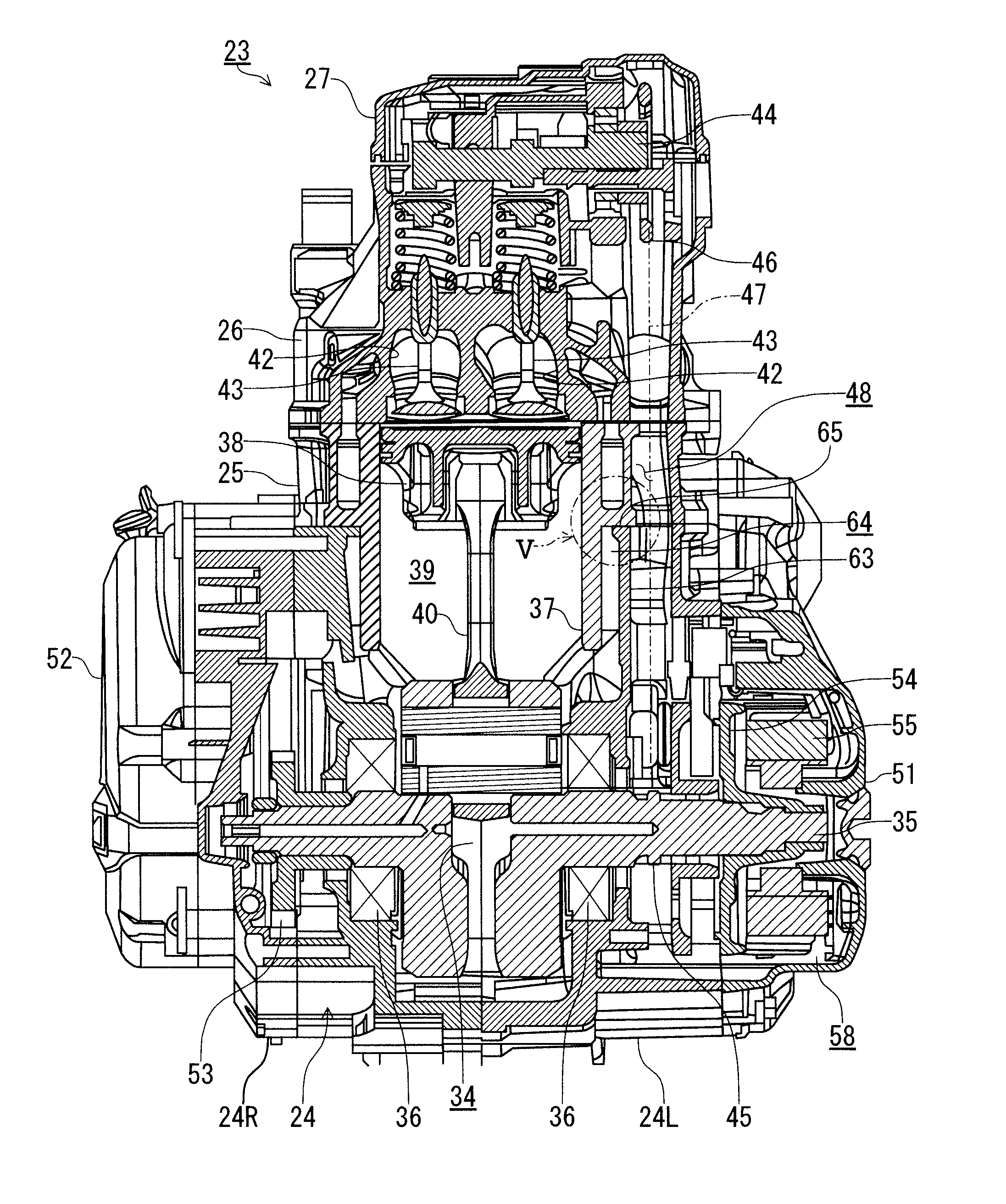
The present invention aims to prevent excessive negative pressure in an internal combustion engine when the piston moves from the bottom dead center to the top dead center. The invention provides a space, called the communicating member, between the cylinder and the crank case unit to allow air and lubricant oil to flow without being blocked by droplets of lubricant oil. This helps to prevent excessive negative pressure and ensures reliable operation of the engine.

Problems solved by technology

However, the internal combustion engine described in Patent Document 1 has such a disadvantage as that the balancing hole is closed when the piston is positioned at a bottom position of the cylinder, and in such occurrence, the negative pressure in the crank chamber cannot be effectively prevented until the balancing hole has been opened even if the piston is being lifted.
However, in a certain case, the engine lubricant oil used for the internal combustion engine may be contained with abrasion particles produced by abrasion of the cylinder or other components, and the abrasion particles may block the balancing hole.

Method used


Image

  • Internal combustion engine
  • Internal combustion engine
  • Internal combustion engine

Examples


Embodiment Construction

[0025]In the following, a best mode carrying out the present invention will be described with reference to the accompanying drawings. Further, it is to be noted that terms “upper”, “lower”, “right”, “left” and the like terms are used herein with reference to illustrations on the accompanying drawings or in an actually installed state of an internal combustion engine to a motorcycle.

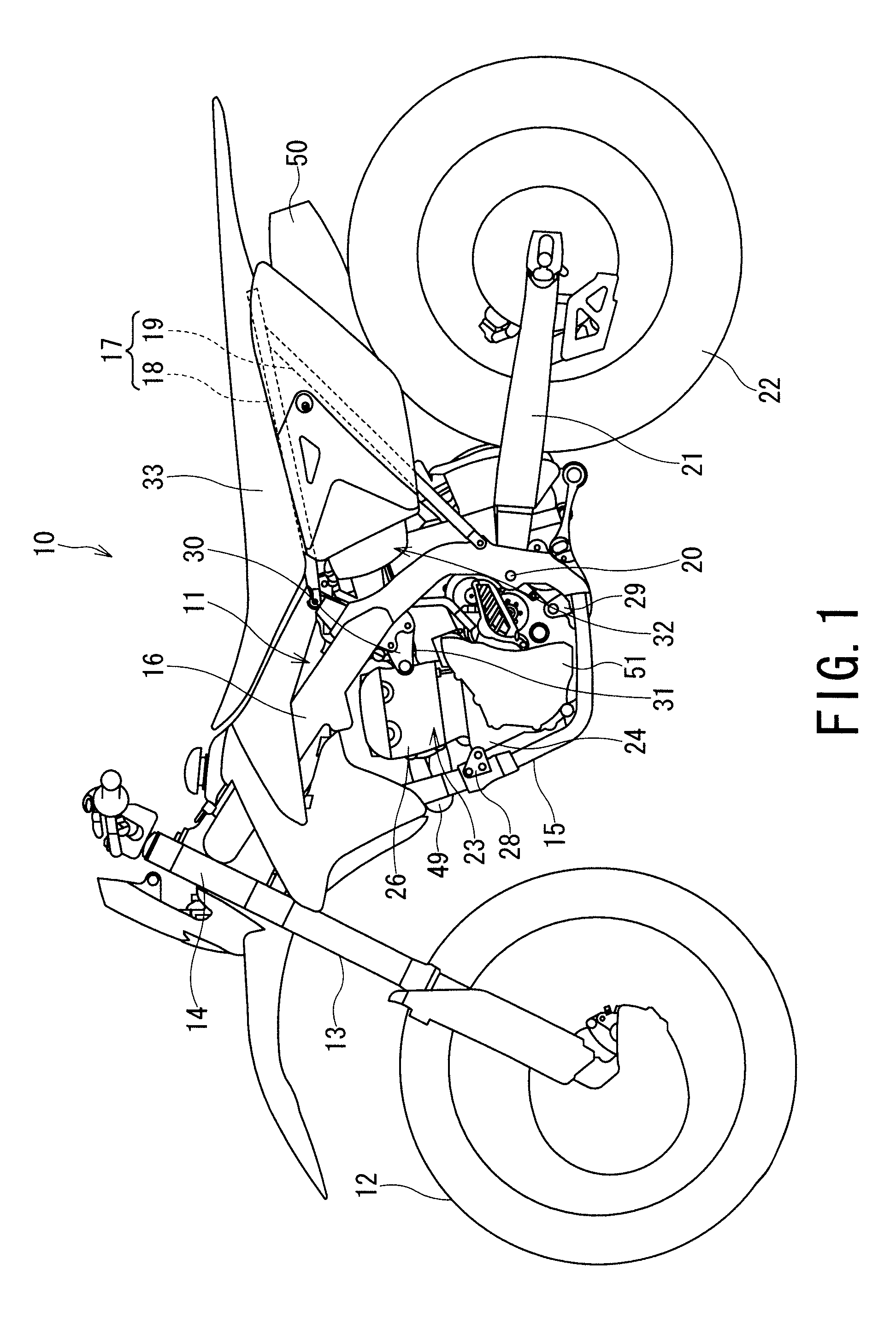
[0026]A motorcycle 10 shown in FIG. 1 is a vehicle capable of off-road riding type, for example, mounted with a single cylinder four stroke engine.

[0027]The motorcycle 10 is equipped with a head pipe 14 at a front portion of a vehicle frame 11 (i.e., body frame 11), and the head pipe 14 supports a front fork 13 and a front wheel 12 to be swiveled with respect to the vehicle body.

[0028]A down tube 15 extending downward and a main frame 16 extending rearward are attached, for example, by means of welding, to the rear portion of the head pipe 14. The down tube 15 once extending downward is then bent to the r...


PUM


Abstract

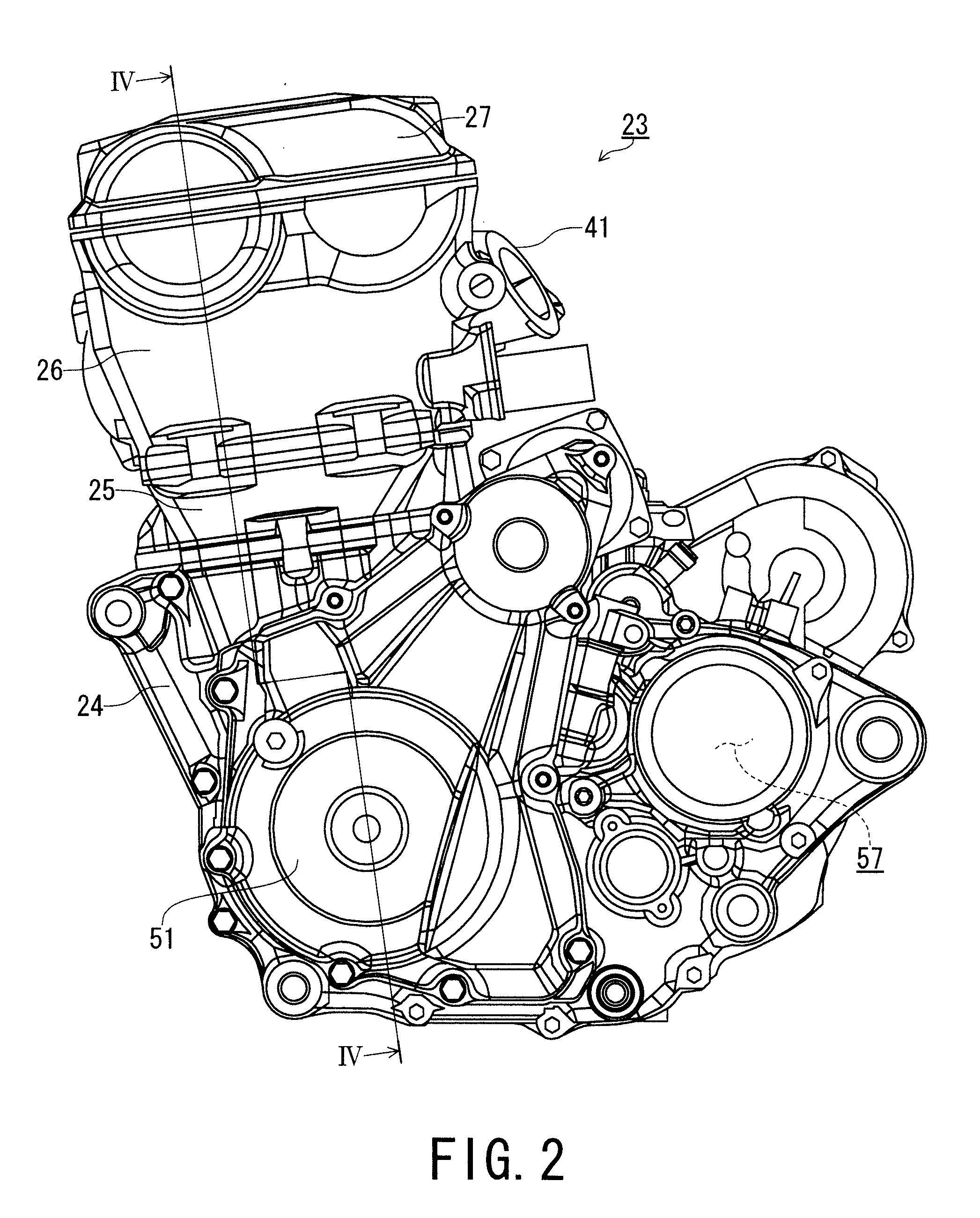
An internal combustion engine includes a crankcase unit forming a crank chamber, a cylinder having a cylinder bore and a projecting portion extending toward the crankcase unit so as to be coupled thereto, a piston that reciprocates in the cylinder bore of the cylinder provided with the projecting portion. The crankcase unit has a wall section and a space is formed between the projecting portion of the cylinder and the wall section of the crankcase unit when the crank case unit and cylinder having the projecting portion is coupled, and the space formed between the projecting portion of the cylinder and the wall section of the crankcase unit and an outside space of the crank chamber are communicated by a communicating groove which is provided to at least either one of the cylinder and the crankcase unit.

Description

CROSS-REFERENCE TO RELATED APPLICATIONS[0001]The present application claims the benefit of priority to Japanese Patent Application No. 184812 / 2009 filed 7 Aug. 2009, the contents of which are incorporated herein by reference in their entirety.BACKGROUND OF THE INVENTION[0002]1. Field of the Invention[0003]The present invention relates to an internal combustion engine specifically including a crank chamber having a closed structure.[0004]2. Related Art[0005]In general, an engine includes a piston, and for a conventional four stroke engine, when a piston moves from the bottom dead center to the top dead center in a cylinder, a negative pressure is produced in the closed crank chamber to prevent the lifting of the piston. Against such defective matter, a conventional technology provided a solution, for example, disclosed in Patent Document 1 (Japanese Patent Application Laid-Open Publication No. 61-182406), which discloses an internal combustion engine, in which a balancing hole is for...

Claims


Application Information

Patent Timeline
Patent Type & Authority Patents(United States)
IPC IPC(8): F02B75/22
CPCF02F1/102F02F7/0004F02B67/06
Inventor KATAOKA, HIROKI
Owner SUZUKI MOTOR CORP
Learn More