
Packing and seal structure of battery module

a battery module and sealing technology, applied in the field of packaging and sealing structure of batteries, can solve the problems of inability to provide the desired sealing performance, and achieve the effect of suppressing positional displacement and ensuring the desired sealing performan

Active Publication Date: 2017-05-09
OHTSUKA POLY TECH +1
View PDF22 Cites 1 Cited by
  • Summary
  • Abstract
  • Description
  • Claims
  • Application Information

AI Technical Summary

Benefits of technology

[0007]The present invention has been made in view of the above problem and an object thereof is to provide a packing and a seal structure of a battery module using the packing, which can suppress a positional displacement of an extension end of a seal lip part.

Problems solved by technology

Accordingly, extension ends of the first seal lip part and the second seal lip part are displaced in the direction intersecting with the sealing direction, respectively, and thus a desired sealing performance may not be provided due to a positional displacement of the extension ends.

Method used


Image

  • Packing and seal structure of battery module
  • Packing and seal structure of battery module
  • Packing and seal structure of battery module

Examples


Embodiment Construction

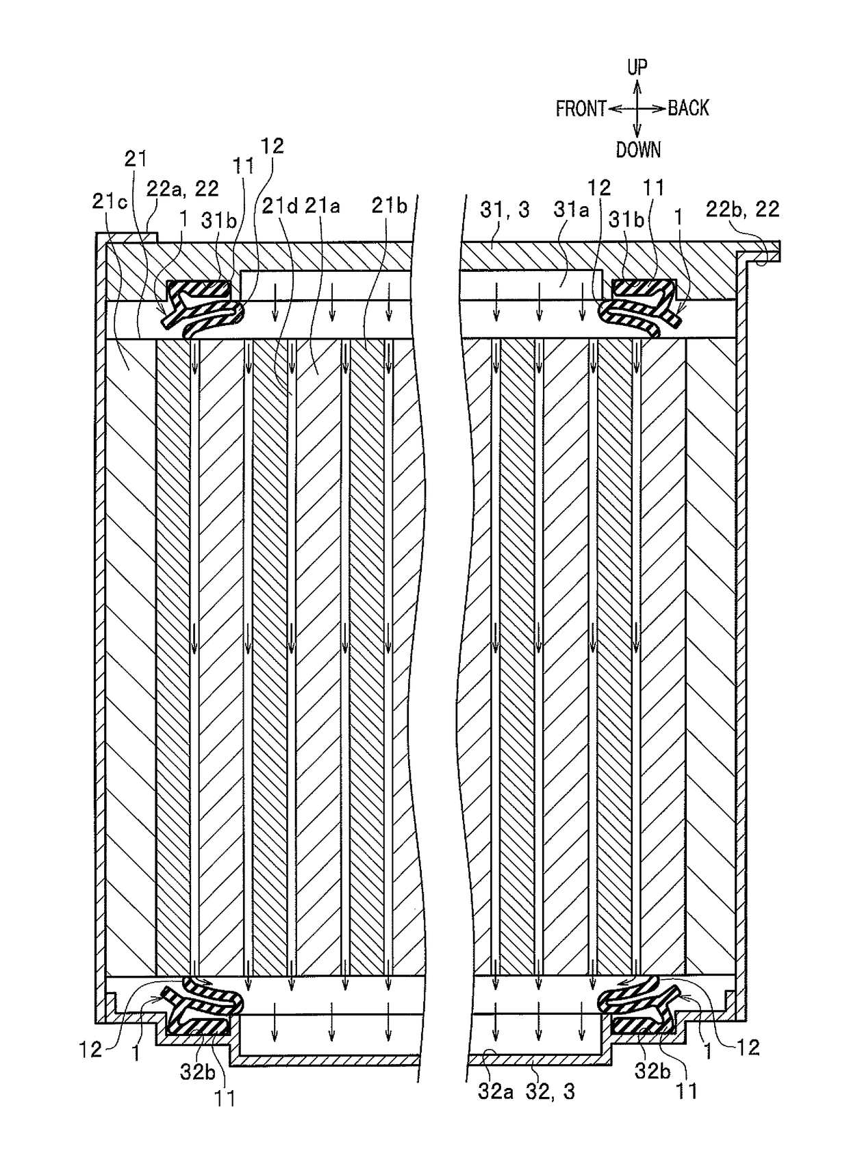
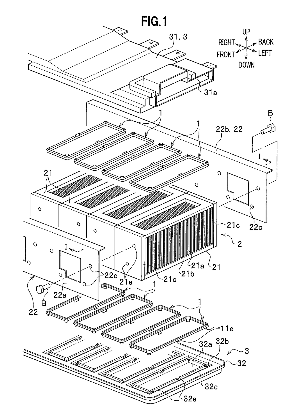
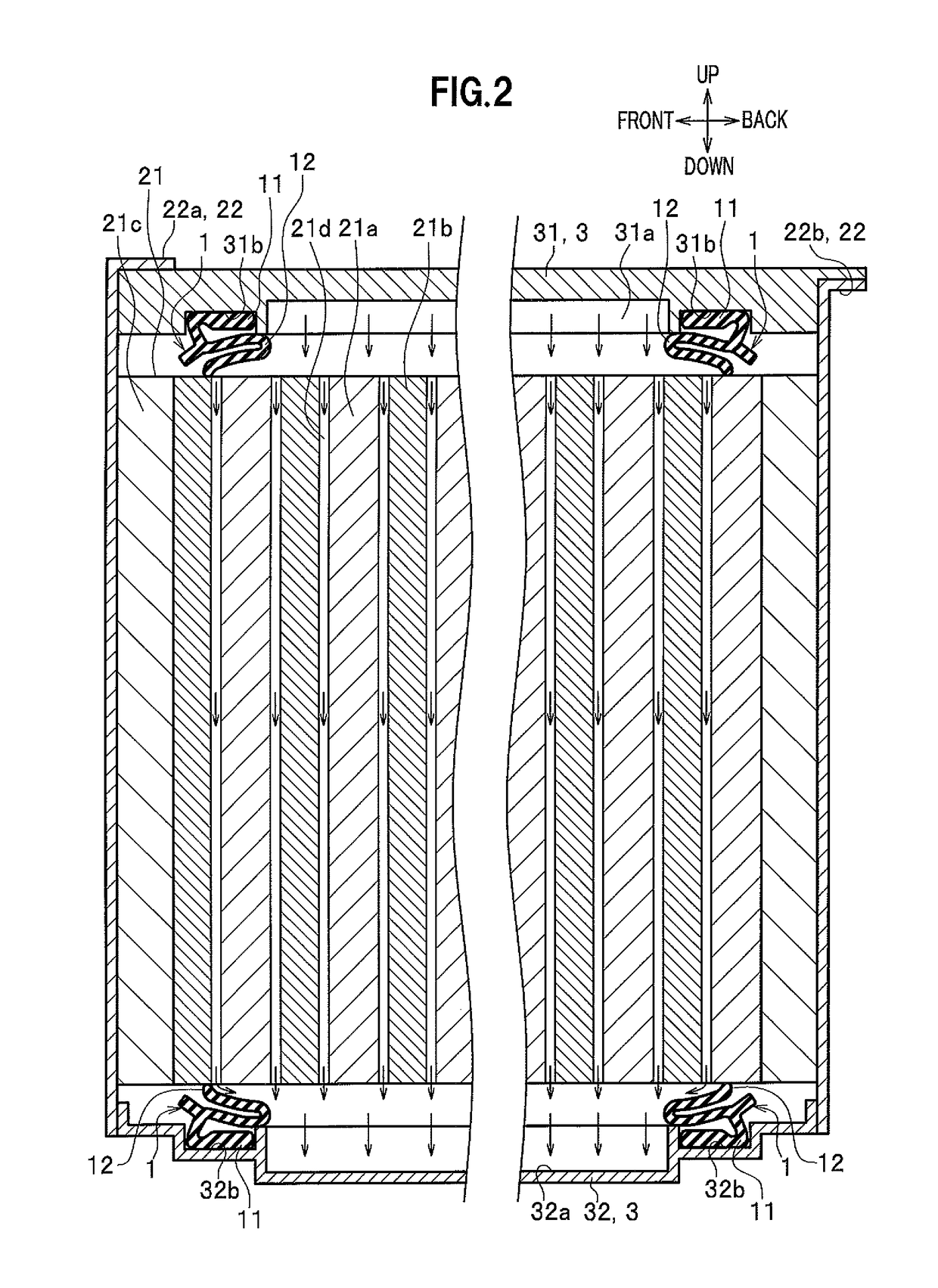
[0038]Hereinafter, an embodiment of the present invention will be described in detail with reference to the drawings when necessary. Note that “front-back”, “up-down”, and “right-left” indicated by arrow marks in each figure represent a front-back direction of a vehicle, an up-down direction of the vehicle, and a right-left direction (width direction of the vehicle) viewed from a driver's seat, respectively.

[0039]In the present embodiment, a description will be given of a case where a packing according to the present invention is applied to a seal structure of a battery pack (battery module) and a duct.

[0040]Prior to a description of a packing 1, a description will be given of configurations of a battery pack 2 and a duct 3 which are the target to be sealed. The battery pack 2 and the duct 3 are mounted, for example, on a vehicle such as a hybrid vehicle or an electric vehicle, and are arranged under a floor (not shown).

[0041]As shown in FIG. 1, the battery pack 2 is provided with a...


PUM

PropertyMeasurementUnit
surface shapeaaaaaaaaaa
curvatureaaaaaaaaaa
shapeaaaaaaaaaa

Abstract

A packing includes a base part that is attached to a duct, and a seal lip part that extends from the base part toward a battery module to press against the battery module. A first bend portion is provided midway in the seal lip part. A second bend portion is provided in a continuous portion between the base part and the seal lip part. The first bend portion and the second bend portion are bent in a direction opposite to each other.

Description

CROSS-REFERENCE TO RELATED APPLICATION[0001]This application is based upon and claims the benefit of priority to the Japanese Patent Application No. 2013-242990, filed on Nov. 25, 2013, the entire contents of which are incorporated herein by reference.BACKGROUND OF THE INVENTION[0002]1. Field of the Invention[0003]The present invention relates to a packing and a seal structure of a battery module using the packing.[0004]2. Description of the Related Art[0005]Conventionally, a packing of every sort and kind that seals a space between two members has been developed. This kind of packing is described, for example, in Patent Document 1: Japanese Patent Application Publication No. 2004-116101. The packing described in Patent Document 1 is provided with a base part that is extended along a direction intersecting with a sealing direction, a first seal lip part that is bent from one end of the base part to extend toward one member, and a second seal lip part that is bent from the other end ...

Claims


Application Information

Patent Timeline
Patent Type & Authority Patents(United States)
IPC IPC(8): F16J15/06F16J15/02H01M2/10H01M10/6563H01M10/6556H01M50/183H01M50/209
CPCF16J15/022F16J15/025H01M2/1077H01M2/1094H01M10/6556H01M10/6563H01M50/183H01M50/209Y02E60/10H01M50/24
Inventor UCHIDA, YOSHITAKASUGIZAKI, TETSUYAHIGAKI, TOMOHIRO
Owner OHTSUKA POLY TECH
Learn More