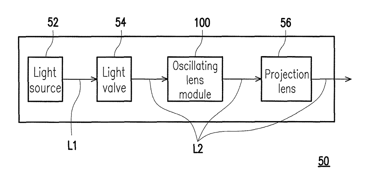
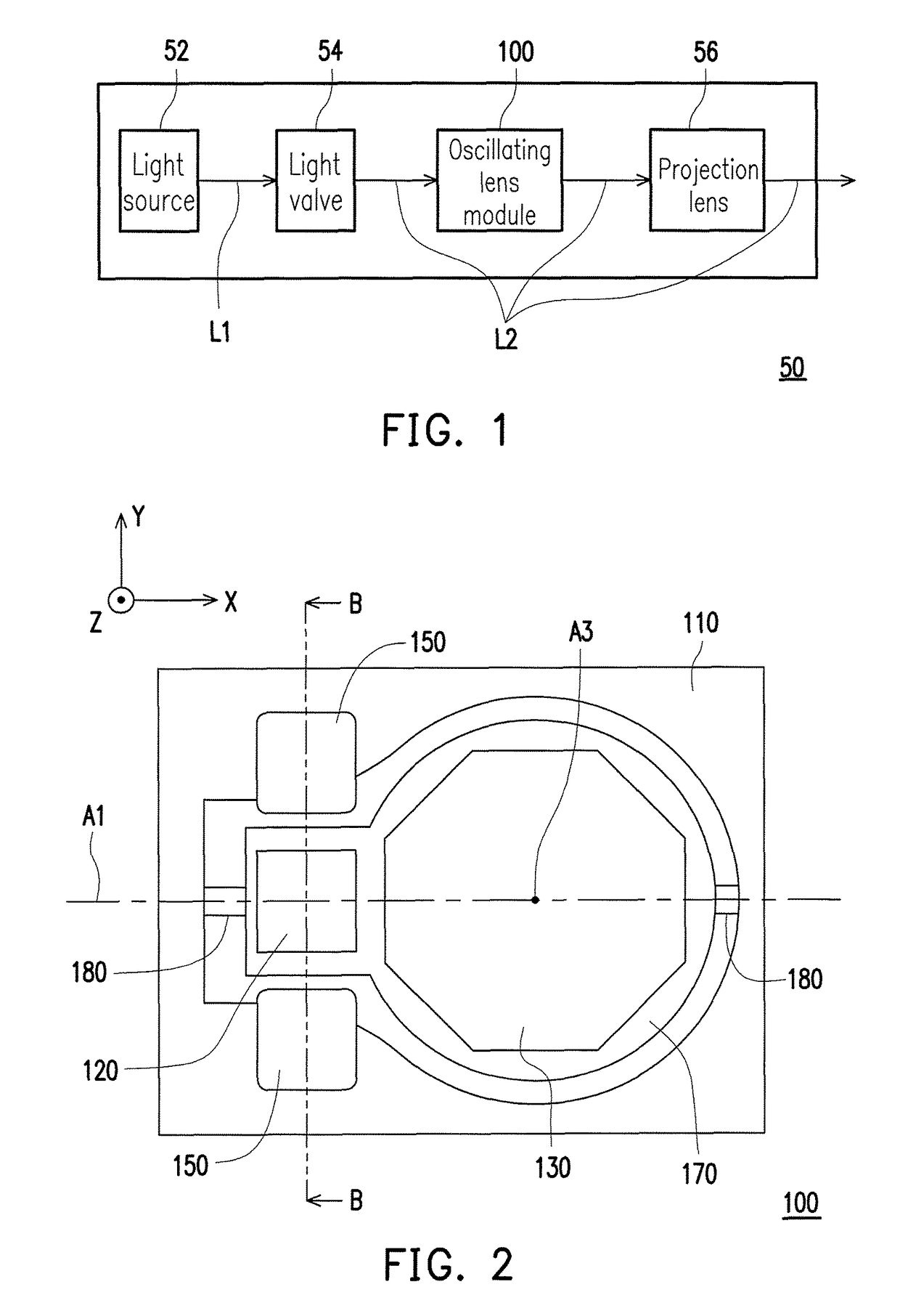
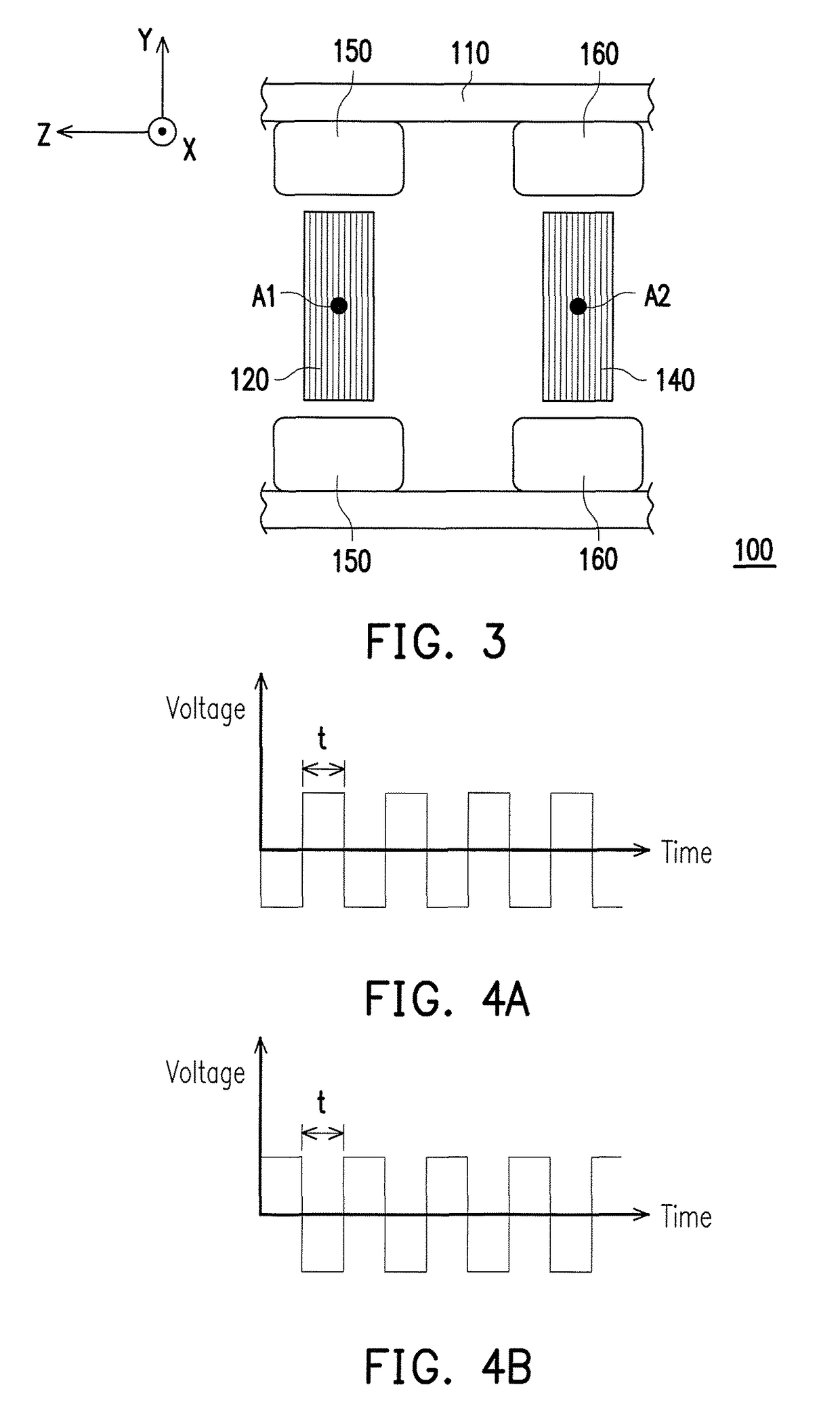
Oscillating lens module and projector

a technology of optical lens and projector, which is applied in the field of optical lens module and projector, can solve the problems of project image shake and vibrating noise, and achieve the effect of preventing over-vibration

Active Publication Date: 2018-09-18
CORETRONIC
View PDF14 Cites 1 Cited by
  • Summary
  • Abstract
  • Description
  • Claims
  • Application Information

AI Technical Summary

Benefits of technology

[0008]The invention provides an oscillating lens module and a projector, in which the projector is prevented from over vibrating caused by the oscillating lens module.
[0012]Based on the above, the embodiments of the invention have at least one of the advantages or effects below. In the oscillating lens module of the invention, except for disposing the first coil which is used to drive the lens to oscillate, the second coil corresponding to the first coil is further disposed, and the oscillation phase of the second coil is configured to be opposite to the oscillation phase of the first coil. Accordingly, when the oscillating lens module actuates, the vibration applied on the frame via the first coil could be counterbalanced by the vibration applied on the frame via the second coil. Thus, the vibration of the oscillating lens module is eliminated before transferring to other structures of the projector, such that the projector is prevented from over vibrating caused by the oscillating lens module, so as to guarantee that shaking of the projection image and excessive vibrating noise are not generated during the operation of the projector.

Problems solved by technology

Simultaneously, the influence of the oscillation generated by the coil is transferred to other structures of the projector to cause the resonance of the projector, which makes the projection image shake and makes vibrating noise.

Method used


Image

  • Oscillating lens module and projector
  • Oscillating lens module and projector
  • Oscillating lens module and projector

Examples


Embodiment Construction

[0021]In the following detailed description of the preferred embodiments, reference is made to the accompanying drawings which form a part hereof, and in which are shown by way of illustration specific embodiments in which the invention may be practiced. In this regard, directional terminology, such as “top,”“bottom,”“front,”“back,” etc., is used with reference to the orientation of the Figure(s) being described. The components of the invention can be positioned in a number of different orientations. As such, the directional terminology is used for purposes of illustration and is in no way limiting. On the other hand, the drawings are only schematic and the sizes of components may be exaggerated for clarity. It is to be understood that other embodiments may be utilized and structural changes may be made without departing from the scope of the invention. Also, it is to be understood that the phraseology and terminology used herein are for the purpose of description and should not be ...


PUM


Abstract

The invention discloses an oscillating lens module and a projector. The oscillating lens module includes a frame, a first coil, a lens, and a second coil. The first coil and the second coil are connected to the frame and located in a magnetic field, wherein the first coil and the second coil are adapted to be electrified and to oscillate about a first axis and a second axis respectively via the magnetic field. The lens is connected to the first coil, wherein the lens is adapted to oscillate along with the first coil. An oscillation phase of the second coil is opposite to an oscillation phase of the first coil, such that forces applied on the frame by the first coil and the second coil are counterbalanced, so as to prevent the oscillating lens module from over vibrating which makes projection images shake and makes noise.

Description

CROSS-REFERENCE TO RELATED APPLICATION[0001]This application claims the priority benefit of China application serial no. 201510375771.3, filed on Jul. 1, 2015. The entirety of the above-mentioned patent application is hereby incorporated by reference herein and made a part of this specification.BACKGROUND OF THE INVENTION[0002]Field of the Invention[0003]The invention relates to a lens module and a projector, more specifically, relates to an oscillating lens module and a projector having the oscillating lens module.[0004]Description of Related Art[0005]The imaging principle of the projector is that the illumination light beam generated by the light source is converted to the image light beam via the light valve, and then the image light beam is projected through the projection lens to a screen or a wall to form an image. With improvements in projector technology and a drop in manufacturing costs, applications of projectors have gradually expanded from commercial use to household use...

Claims


Application Information

Patent Timeline
Patent Type & Authority Patents(United States)
IPC IPC(8): G03B21/14G03B5/00
CPCG03B21/142G03B5/00G03B2205/0069
Inventor WU, SHANG-HSUANGLIN, TSUNG-CHINGCHOU, CHIH-CHENG
Owner CORETRONIC
Why Eureka
Try Eureka