
Compact ballpoint pen

a ballpoint pen and compact technology, applied in the field of compact ballpoint pen, can solve the problem of difficulty in taking a long ballpoint pen out of a pocket, and achieve the effects of reducing manufacturing costs, less fatigue, and increasing writing speed using the compact ballpoint pen of the present invention

Active Publication Date: 2018-09-25
LEE MOON KEY
View PDF16 Cites 0 Cited by
  • Summary
  • Abstract
  • Description
  • Claims
  • Application Information

AI Technical Summary

Benefits of technology

The present invention is a compact ballpoint pen that is smaller than conventional ballpoint pens, requiring less materials and inducing less fatigue while writing. It is also lighter, allowing for faster writing. Additionally, the compact ballpoint pen is designed with a small inertial moment, making it easier to start writing immediately after pressing a button. Kids with small hands may also use it more efficiently and quickly.

Problems solved by technology

In general, it is difficult to take a long ballpoint pen out of a pocket because the long ballpoint pen is easily trapped when being put into a hip pocket of blue jeans or an inside pocket of a jacket.
Further, in order to use a conventional ballpoint pen, a user has to grasp the ballpoint pen and move a thumb to push a button to take a nib out of a case of the ballpoint pen, and inconveniently move a hand to a ball nib side from a button side to write.

Method used


Image

  • Compact ballpoint pen
  • Compact ballpoint pen
  • Compact ballpoint pen

Examples


embodiment 1

[0029

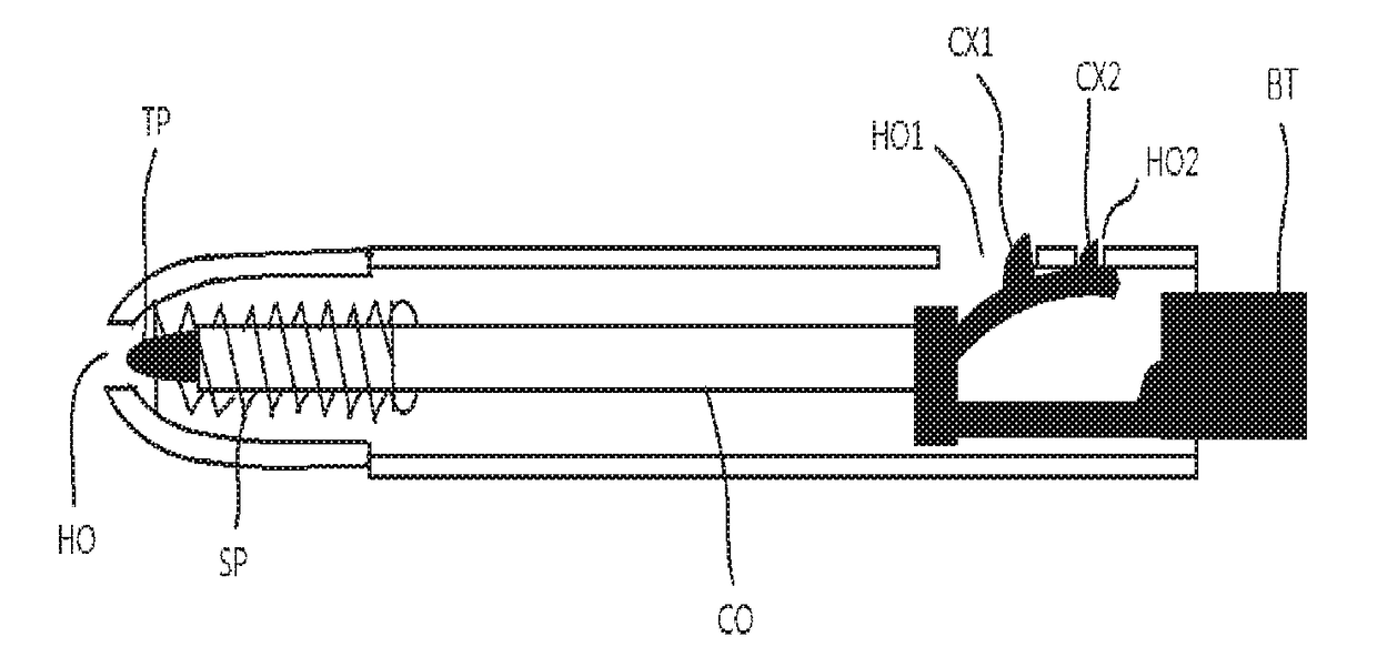
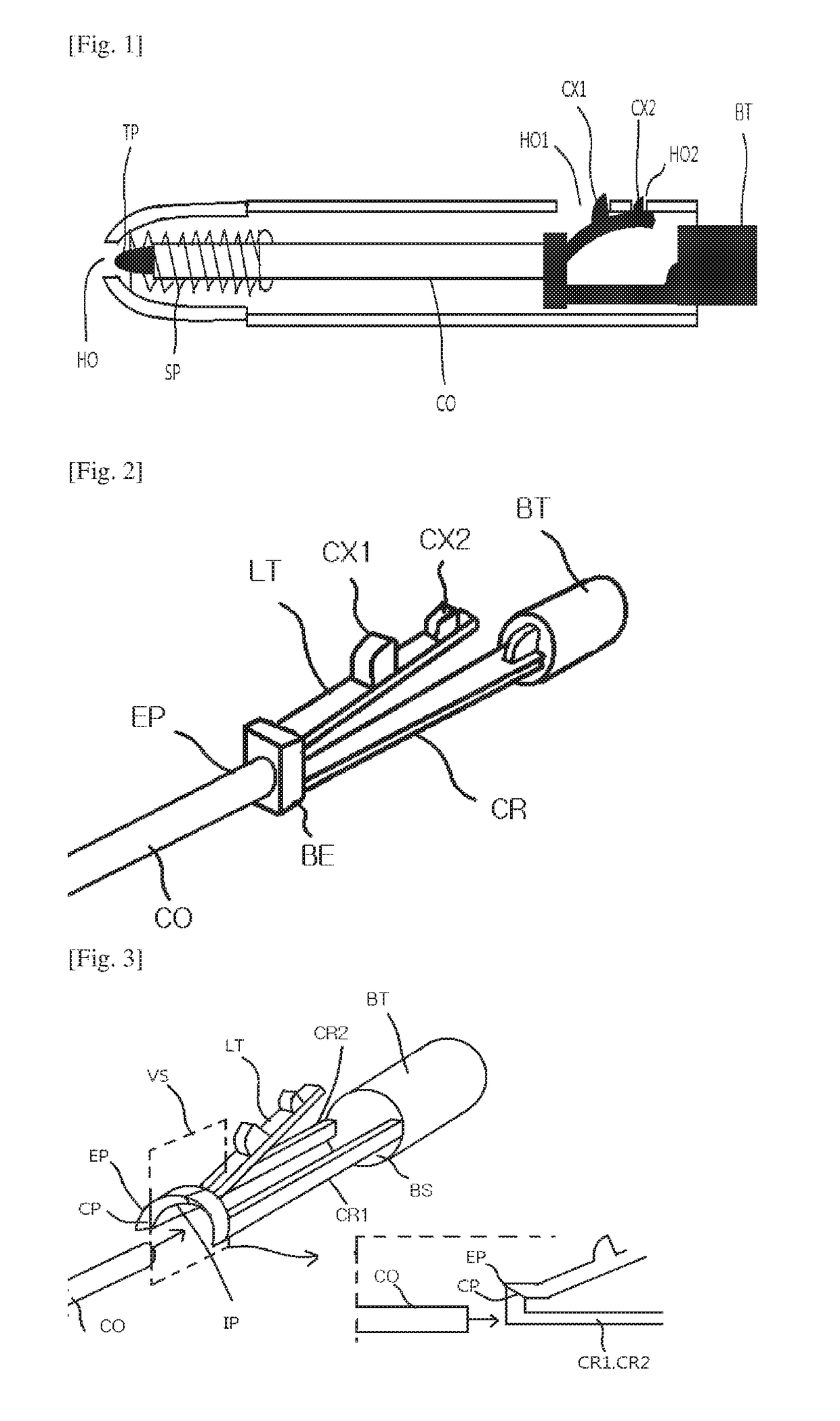
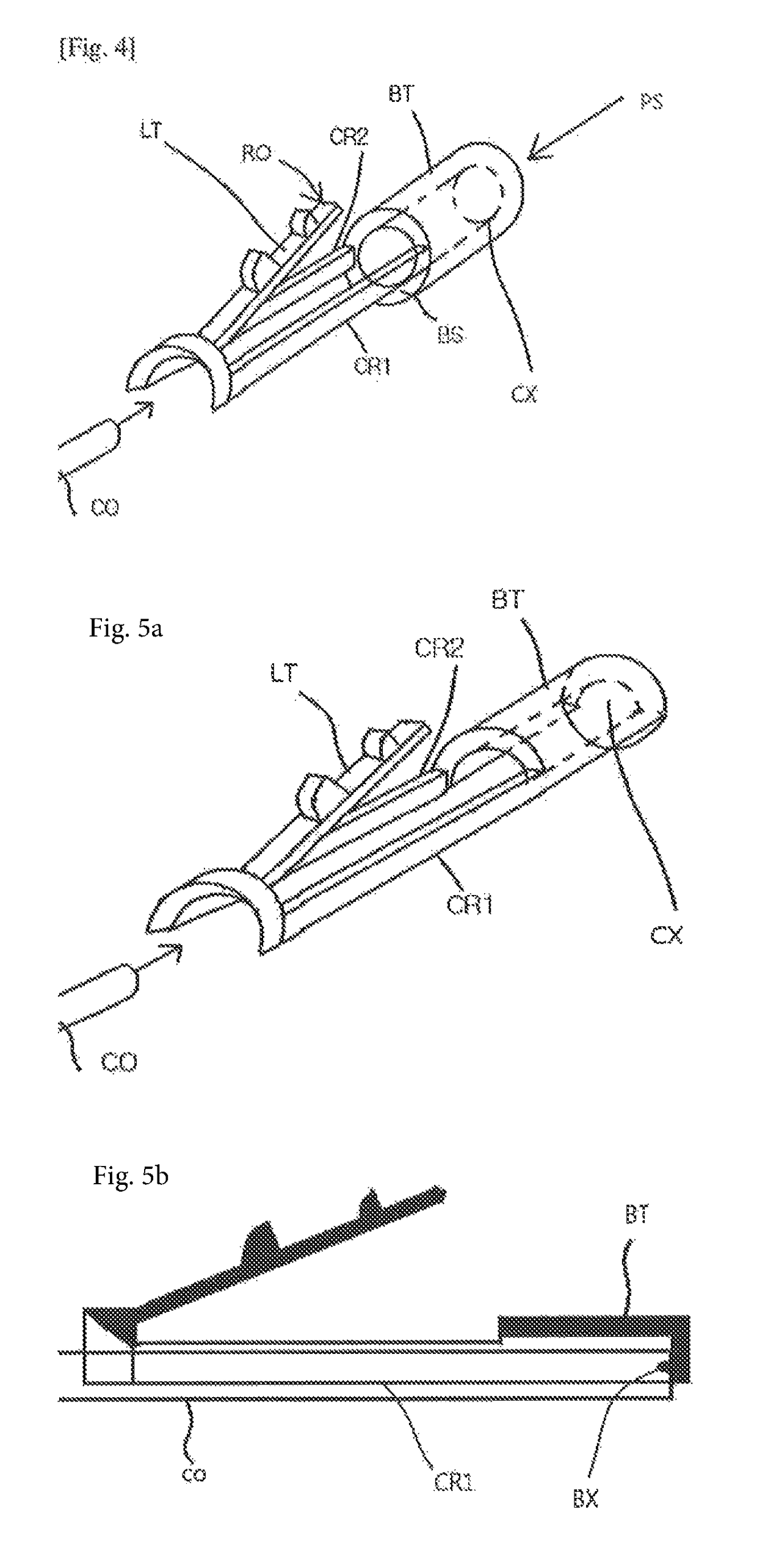
[0030]FIG. 1 is a cross-sectional view of a conventional ballpoint pen (Monami 153 ballpoint pen), and FIG. 2 is a magnified view of a button. In FIG. 2, an end point EP of a ballpoint pen ink cartridge CO, which is opposite to a nib TP of the ballpoint pen ink cartridge CO, is in contact with a bottom end BE of a push button having a V shape. A first bar and a second bar CR are attached to the bottom end BE of the V-shaped push button. The first bar includes an elastic latch LT formed thereon and the second bar includes a cylindrical cap BT attached thereto. The latch LT includes a first protruding part CX1 and a second protruding part CX2 having a fan shape. The protruding parts are respectively inserted into two holes HO1 and HO2 formed in a ballpoint pen case (a pipe-shaped body of the ballpoint pen). If the cylindrical cap BT is pushed into the ballpoint pen case then the nib TP of the ballpoint pen ink cartridge of the ballpoint pen comes out of a hole HO of the ballpoint...

embodiment 2

[0040

[0041]Among existing ballpoint pens, there are products in which a nib of a ballpoint pen protrudes out of a case when a button is pressed once and the nib retreats into the case when the same button is pressed again. FIG. 7 is a cross-sectional view of the ballpoint pen described above. FIG. 8 illustrates a structure of the button of the ballpoint pen. In FIG. 8, concave grooves LH are formed in an inner surface of a ballpoint pen case CS so that convex portions PX and MX of a push button may be inserted into the is concave grooves LH. FIG. 8 is a cross-sectional view of the ballpoint pen case CS cut by a plane passing an axis of the ballpoint pen case CS. The push button includes an upper push portion EB and an inner rotating portion RP which is inserted into a lower side of the upper push portion EB. The upper push portion EB is exposed to the outside so as to be pushed by a hand. A ballpoint pen ink cartridge CO is inserted into the inner rotating portion RP. A surface wher...


PUM


Abstract

A compact ballpoint pen in which a bar of a push button is split into left and right bars and thus an ink cartridge can be inserted into a space between the split bars. Thus, the length of a ballpoint pen is reduced.

Description

TECHNICAL FIELD[0001]The present invention relates to a compact ballpoint pen which may be easily put into a small pocket to be conveniently carried.BACKGROUND ART[0002]FIG. 13 illustrates a position UP of a hand when a thumb pushes a button of conventional long ballpoint pen. FIG. 14 illustrates a position DP of the hand to write with the ballpoint pen, where the hand is moved to a nib side that is the opposite side of the button. In general, it is difficult to take a long ballpoint pen out of a pocket because the long ballpoint pen is easily trapped when being put into a hip pocket of blue jeans or an inside pocket of a jacket.[0003]Further, in order to use a conventional ballpoint pen, a user has to grasp the ballpoint pen and move a thumb to push a button to take a nib out of a case of the ballpoint pen, and inconveniently move a hand to a ball nib side from a button side to write.DETAILED DESCRIPTION OF THE INVENTIONTechnical Problem[0004]The objective of the present invention ...

Claims


Application Information

Patent Timeline
Patent Type & Authority Patents(United States)
IPC IPC(8): B43K7/00B43K24/08B43K7/12
CPCB43K7/005B43K24/08B43K7/12
Inventor LEE, MOON KEY
Owner LEE MOON KEY
Learn More