Adjustable spherical joint member
a spherical joint and adjustable technology, applied in the direction of connections, basic electric elements, shafts and bearings, etc., can solve the problem of imprecise positioning of the joint, and achieve the effect of stable and secure connection
- Summary
- Abstract
- Description
- Claims
- Application Information
AI Technical Summary
Benefits of technology
Problems solved by technology
Method used
Image
Examples
first embodiment
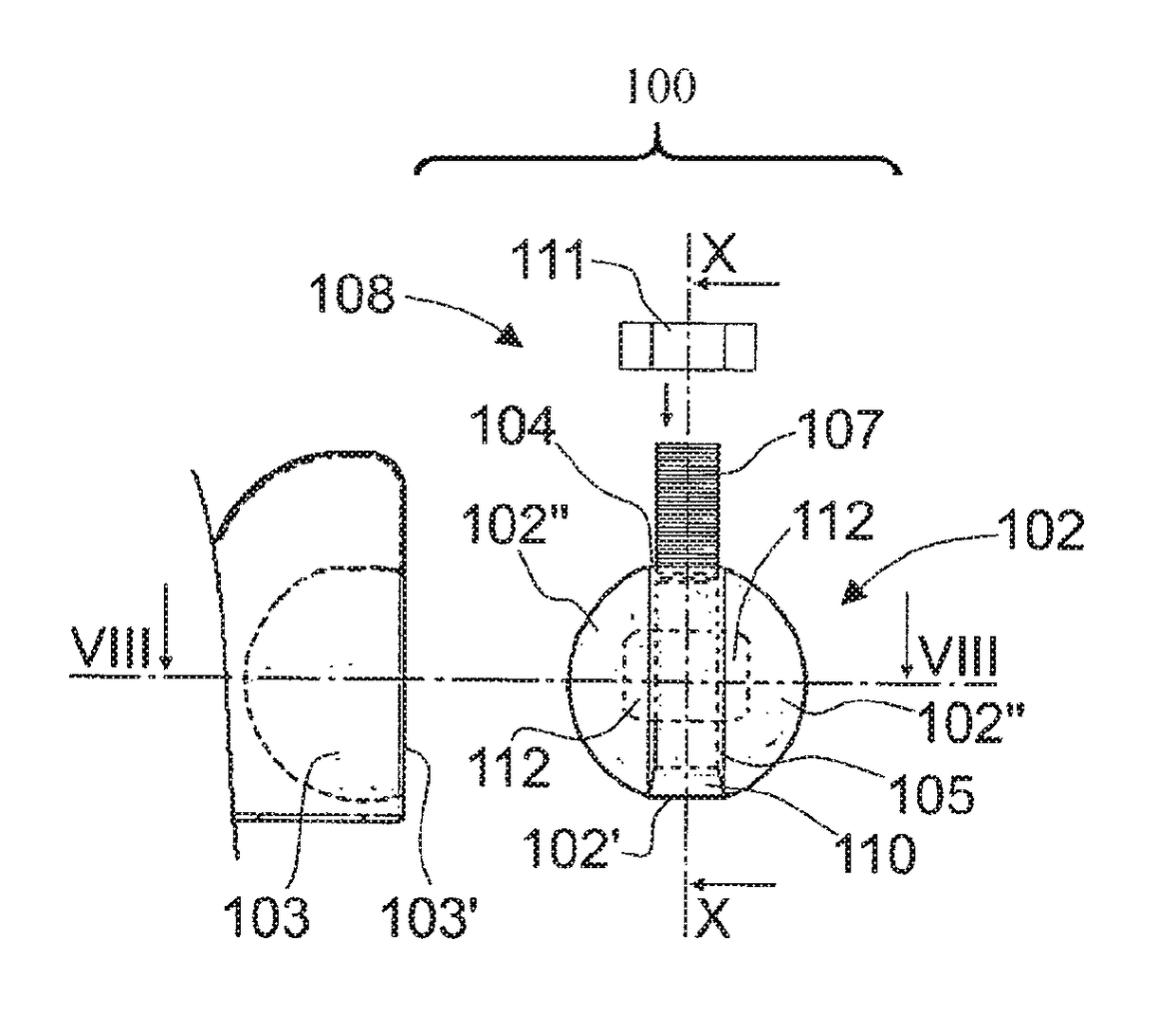
[0078]The configuration of the spherical element 102 is however different with respect to that of the More particularly, the spherical element comprises a substantially cylindrical central portion 102′, between two substantially spherical cap shaped portions 102″.
[0079]The spherical element 102 is sized so that the circular base of each substantially spherical cap shaped portion 102″ matches a respective base of the substantially cylindrical portion 102′. The spherical element 102 can be obtained either enbloc, for example through milling of a portion of the outer surface of the spherical element 102, or through the assembly, in a way known to the skilled person, of many separate components. The substantially cylindrical central portion 102′ has, at its circular cross-section, a radius r shorter than the curvature radius R of each spherical cap 102″, so that the spherical element 102 has reduced overall dimensions in a plane parallel to the bases of such a cylindrical central porti...
second embodiment
[0099]In order to connect one first and one second component to one another through the ball joint 100 according to the present invention, the spherical element 102 is inserted in the respective seat 103 obtained in a first component and the ball joint 100 is connected, through insert 104, to the second component.
[0100]An insert of this type is designed to be housed in a respective hollow seat 103 configured substantially like a spherical cap and, more particularly, having a radius of curvature that is slightly longer than the curvature radius R of the substantially cap-shaped portions 102″ of insert 100, and defining an inlet mouth 103′ with a substantially circular configuration with a radius that is slightly longer than the radius r of the circular section of the substantially cylindrical central portion 102′, but shorter than the radius of curvature R of the substantially cap-shaped portions 102″. The substantially spherical cap-shaped housing seat 103 has a volume that is at le...
third embodiment
[0106]With reference now to FIGS. 10 to 13, it can be noted how a ball joint according to the present invention is indicated with reference numeral 200 and comprises a substantially spherical element 202, designed in use to be positioned inside a respective hollow housing seat 203 obtained in a first component, and an insert 204, connected to the spherical element 202, as will be better described below, and associable, in use, with a second component.
[0107]More particularly, the spherical element 202 comprises a substantially cylindrical central portion 202′, between two substantially spherical cap shaped portions 202″. The spherical element 202 is dimensioned so that the circular base of each substantially spherical cap shaped portion 202″ matches a respective base of the substantially cylindrical portion 202′. The spherical element 202 can be obtained either enbloc, for example through milling of a portion of the outer surface of the spherical element itself, or it can be obtained...
PUM
 Abstract
Description
Claims
Application Information
 - R&D
- Intellectual Property
- Life Sciences
- Materials
- Tech Scout
- Unparalleled Data Quality
- Higher Quality Content
- 60% Fewer Hallucinations
Browse by: Latest US Patents, China's latest patents, Technical Efficacy Thesaurus, Application Domain, Technology Topic, Popular Technical Reports.
© 2025 PatSnap. All rights reserved.Legal|Privacy policy|Modern Slavery Act Transparency Statement|Sitemap|About US| Contact US: help@patsnap.com


