Push fastener

A firmware and pressure technology, applied in the direction of threaded fasteners, connecting components, pins, etc., can solve problems such as poor adhesion and easy falling off

Inactive Publication Date: 2017-02-22
LOCKDOWEL
View PDF7 Cites 3 Cited by
  • Summary
  • Abstract
  • Description
  • Claims
  • Application Information

AI Technical Summary

Problems solved by technology

However, small thin veneer nails and screws adhere poorly to the most typically used materials (c

Method used


Image

  • Push fastener
  • Push fastener
  • Push fastener

Examples


Embodiment Construction

[0020] The above and following description, as well as the drawings of this document, focus on one or more presently preferred embodiments of the invention and also describe some exemplary optional features and / or alternative embodiments. The description and drawings are for purposes of illustration and not limitation. Those of ordinary skill in the art will recognize variations, modifications, and substitutions. Such changes, modifications and substitutions are also within the scope of the present invention. Some titles are abbreviated for convenience only.

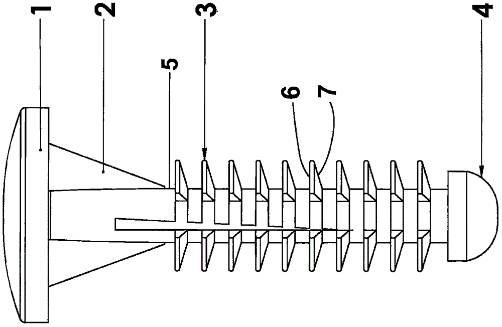
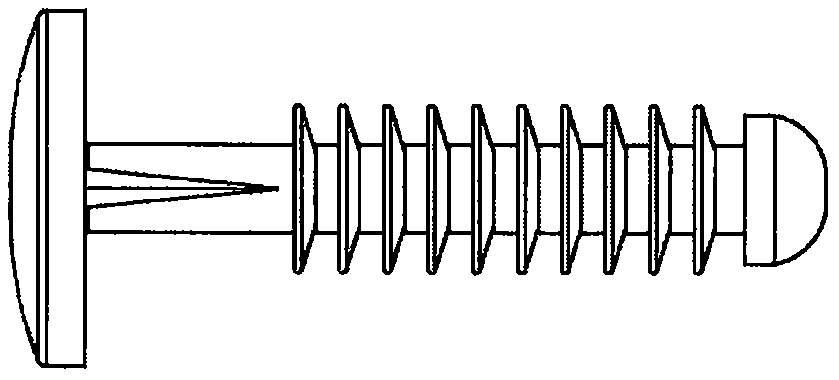
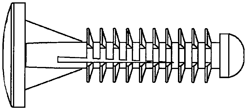
[0021] The present invention includes an all plastic mounting pin construction with a circular tab at the top. figure 1 represents a fastener according to an embodiment of the invention comprising a top arched cap 1 designed for manual pressure, such as thumb or hand pressure, to facilitate pushing in and thus tightening The components fit into the drilled holes in the substrate material used. Attached to the top arc...


PUM


Abstract

A push fastener, comprising: a shaft having a top end and bottom end, the top end integrally connected to a cap; a plurality of barbs spaced along a longitudinal distance of the shaft; and a wedge structure positioned on the shaft between the cap and first barb of the plurality. There is a method of fastening using a push fastener having a shaft including a top end and bottom end, the top end integrally connected to a cap; a plurality of barbs spaced along a longitudinal distance of the shaft; and a wedge structure positioned on the shaft between the cap and first barb of the plurality, the method comprising: inserting the bottom end of the shaft of the push fastener inside a substrate, and applying pressure to the top end of the push fastener.

Description

[0001] Cross References to Related Applications [0002] This application claims the benefit of US Provisional Application No. 61 / 935,328, filed February 3, 2014, which is hereby incorporated by reference in its entirety. technical field [0003] The present invention relates to fasteners, and more particularly, to one-piece fasteners that do not have complementary male and female mating components. The invention also relates to fasteners utilizing barbs, in one form or another, as associated fastening elements. Background technique [0004] Typical construction methods used to manufacture self-assemble cabinets and furniture rely on thin panels of materials such as wood, plastic or cardboard that are attached to the back of the product. The back panel is a very important aspect to the overall structural integrity of the furniture or cabinet. Racking (movement from a square or rectangular shape to a parallelogram shape) of the outer frame of a cabinet, furniture, or other ...

Claims


Application Information

Patent Timeline
IPC IPC(8): F16B19/00
CPCF16B19/002F16B21/084Y10T29/49876F16B19/00
Inventor B·考尔凌
Owner LOCKDOWEL
Why Eureka
Try Eureka