Lifting appliance for binding vertical reinforcement

A technology of vertical steel bars and hangers, applied in the direction of load hanging components, transportation and packaging, etc., can solve the problems of poor binding firmness, low construction efficiency, poor positioning accuracy of steel bar binding, etc., and achieve reasonable structural design and construction The effect of high efficiency and easy operation

Inactive Publication Date: 2014-09-24
CCCC FIRST HARBOR ENG +1
View PDF6 Cites 4 Cited by
  • Summary
  • Abstract
  • Description
  • Claims
  • Application Information

AI Technical Summary

Problems solved by technology

In the prior art, ropes or bolts are generally used for binding and positioning of steel bars. During the hoisting construction process, the steel bars often fall off due to reasons such as poor binding firmness or poor quality of the bolts.
This will not only cause hazard risks to construction personnel, but also pose potential safety hazards. At the same time, the positioning accuracy of steel bar binding is poor, which makes the positioning operation of steel bars cumbersome and low construction efficiency.

Method used


Image

  • Lifting appliance for binding vertical reinforcement
  • Lifting appliance for binding vertical reinforcement

Examples


Embodiment Construction

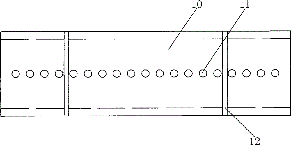
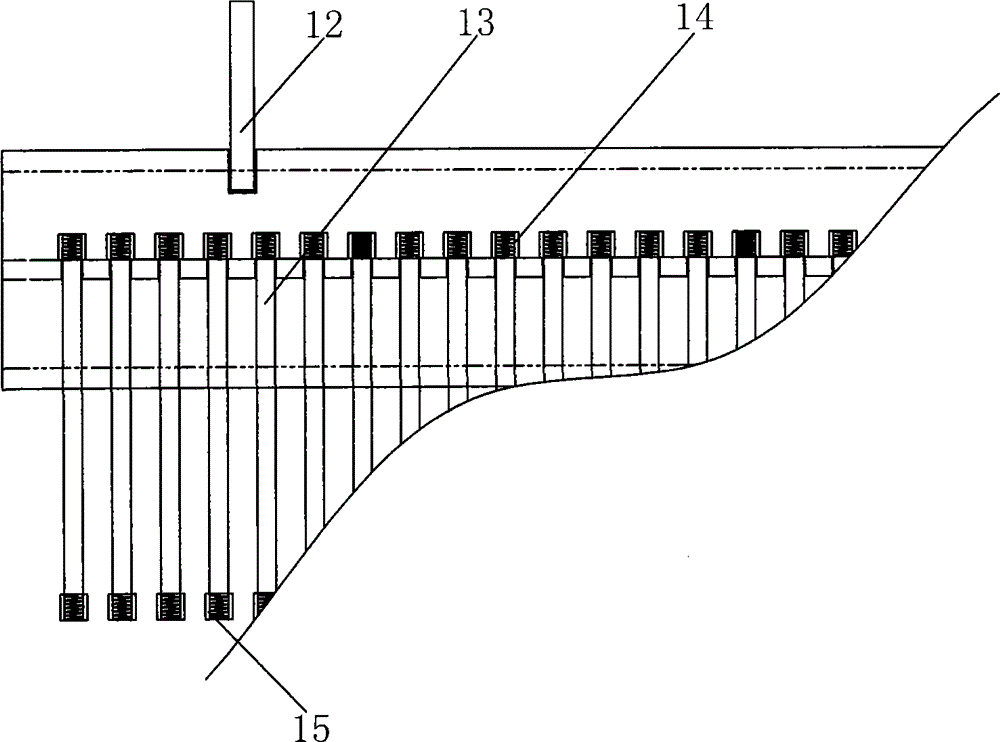
[0015] Such as figure 1 and figure 2 As shown, the vertical steel bar binding hanger has a load-bearing body 10 of a large cross-section I-shaped steel, and a single row of steel bar hoisting holes 11 is provided on the load-bearing body according to the hoisting positions of the vertical steel bars, and each hoisting hole is equipped with a A set of rebar set fixtures. The steel bar suit fixing part comprises the tool bar 13 that vertically passes through in the hoisting hole, the top of the tool bar has a connector, and the lower end of the tool bar is threadedly connected with a steel bar connecting sleeve 15 . The connector is a nut 14 that is sleeved and connected to the top of the tool bar and has a diameter greater than that of the hoisting hole. Two lifting points 12 are symmetrically welded on the bearing body, and the lifting points are lifting lugs welded to the bearing body at both ends of the round steel after the U-shape is completed.


PUM


Abstract

The invention discloses a lifting appliance for binding a vertical reinforcement. The lifting appliance is characterized by comprising a bearing main body, wherein a plurality of reinforcement lifting holes are formed in the bearing main body, a reinforcement sleeving and fixing member is assembled and arranged on each lifting hole, and a lifting point is arranged on the bearing main body. The lifting appliance for binding the vertical reinforcement is reasonable in structure design, suitable for locating and binding multiple longer vertical reinforcements, simple and convenient to operate, high in construction efficiency, and capable of realizing the effect that multiple reinforcements are located and rapidly bound every time.

Description

technical field [0001] The invention belongs to reinforcement cage binding auxiliary equipment for concrete prefabricated parts, in particular to a lifting tool for vertical reinforcement binding and positioning construction. Background technique [0002] As the size and specifications of large reinforced concrete prefabricated parts increase rapidly, the binding and positioning construction of corresponding large steel cages also increases. In the prior art, ropes or bolts are generally used for binding and positioning of steel bars. During the hoisting construction process, the steel bars often fall off due to reasons such as poor binding firmness or poor quality of the bolts. This will not only cause harm risks to construction personnel, but also pose potential safety hazards. At the same time, the positioning accuracy of steel bar binding is poor, which makes the positioning operation of steel bars cumbersome and low construction efficiency. Contents of the invention ...

Claims


Application Information

Patent Timeline
Patent Type & Authority Applications(China)
IPC IPC(8): B66C1/10
Inventor 王伟孙业发夏可强王东升
Owner CCCC FIRST HARBOR ENG
Why Eureka
Try Eureka