Workout bench

a workout bench and bench body technology, applied in the field of workout benches, to achieve the effect of effective exercise of the entire body, efficient time, and convenient movemen

Inactive Publication Date: 2018-10-09
FITBENCH
View PDF57 Cites 15 Cited by
  • Summary
  • Abstract
  • Description
  • Claims
  • Application Information

AI Technical Summary

Benefits of technology

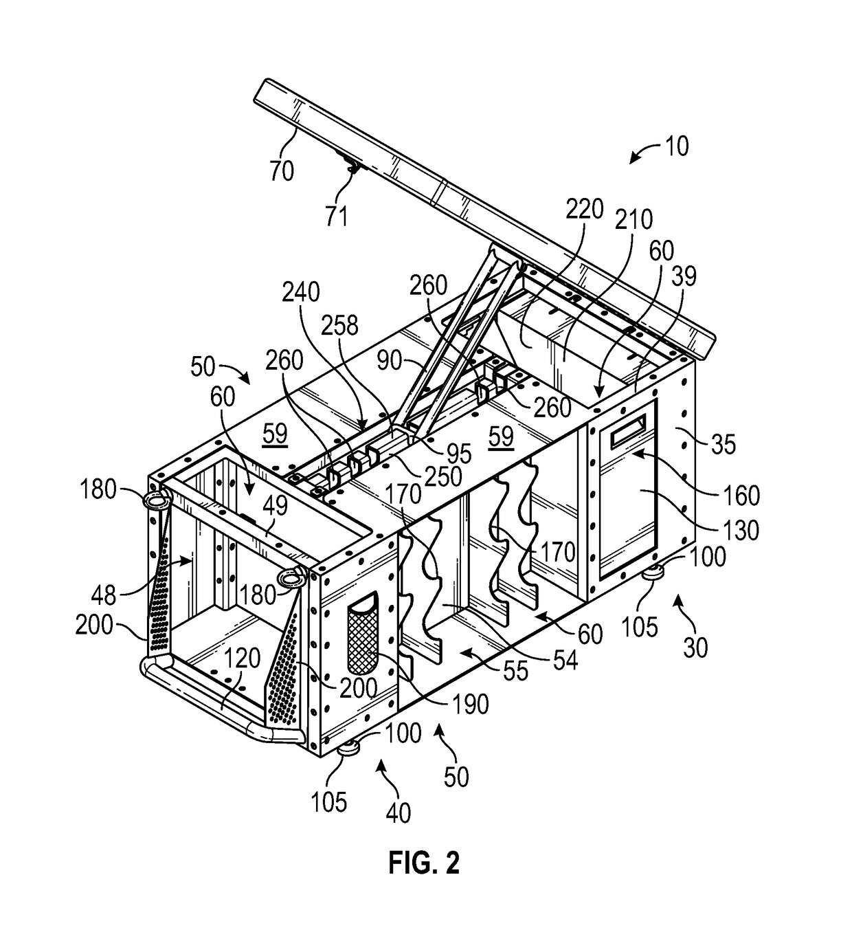
[0008]Preferably, a pair of wheels is fixed with the front container proximate the bottom side and front side thereof, and a handle is fixed with the rear container proximate the bottom side and the rear side thereof. In use, the wheels do not make contact with the support surface when the workout bench is supported by the feet on the support surface. However, when the workout bench is lifted by the handle, the wheels make contact with the support surface, the feet being lifted away from the support surface. Thus, the workout bench is thereby rollable on the support surface.
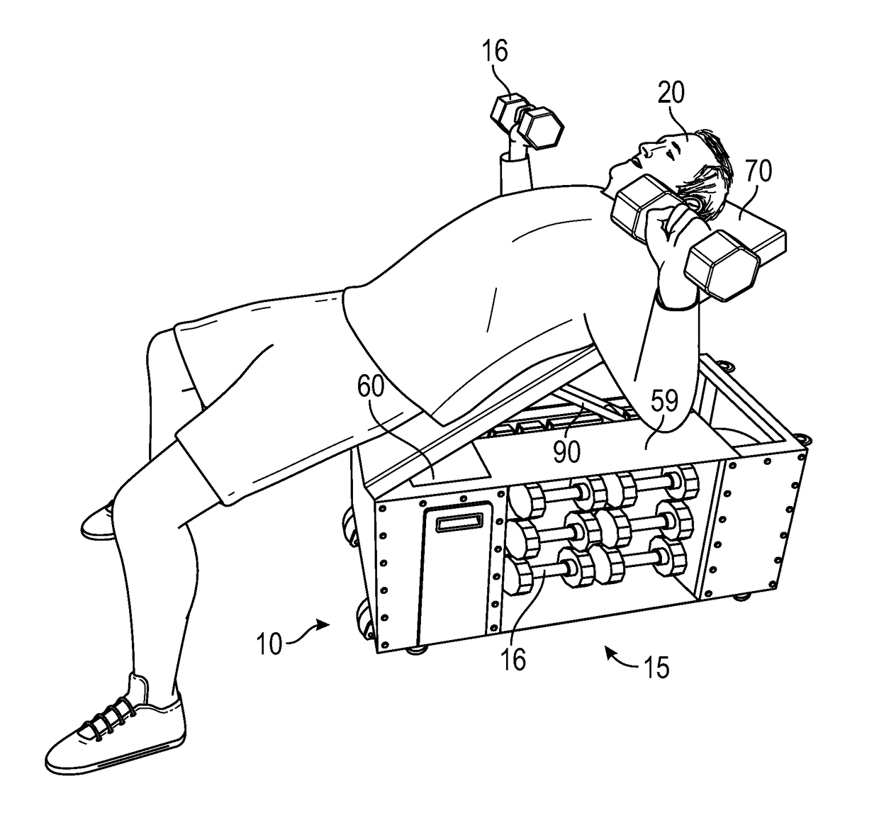
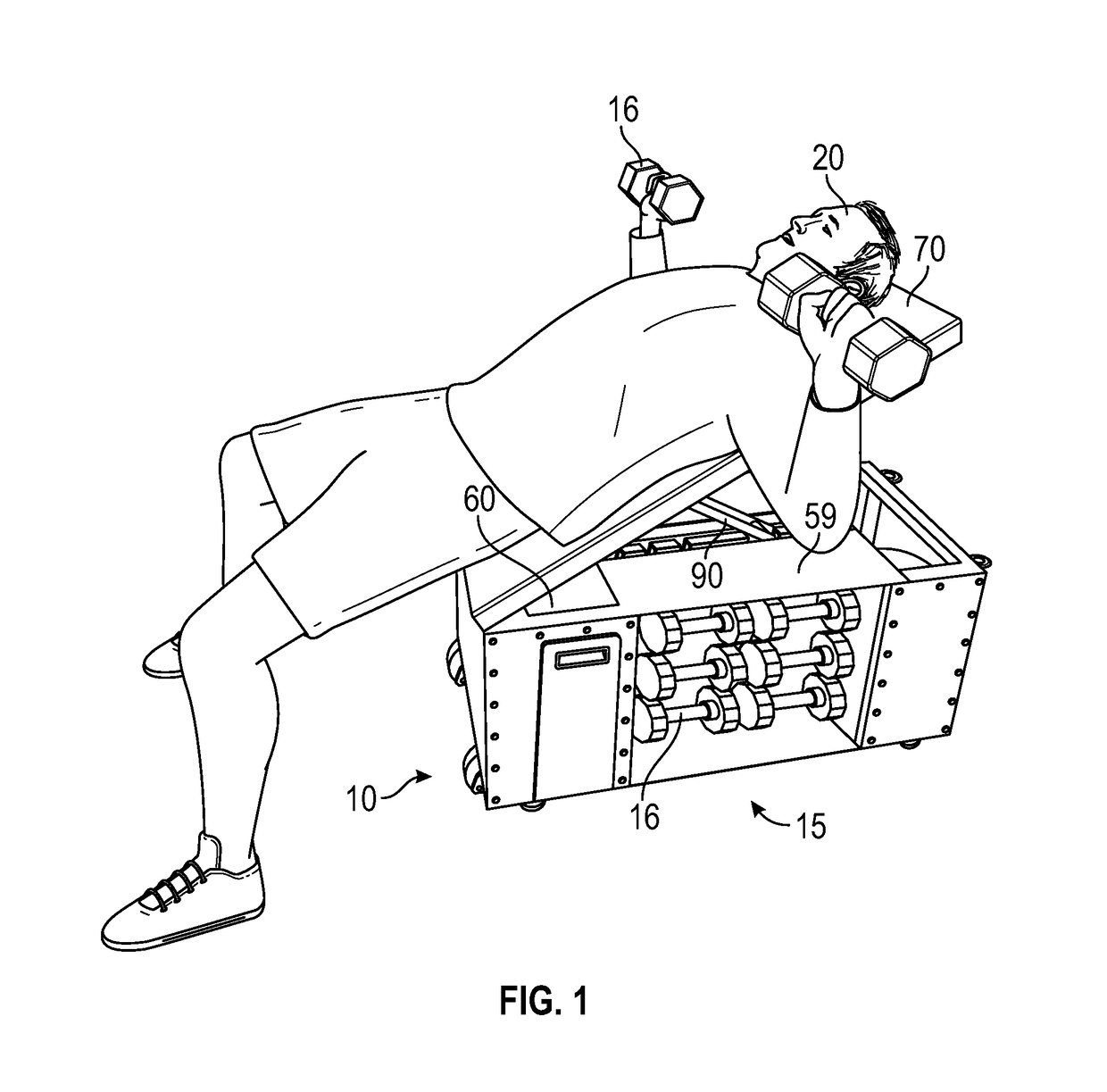
[0010]The present workout bench is compact, portable, easy to move, fully integrated and fully adjustable. This workout bench makes it easy for the user to conduct a complete program of exercise in an efficient amount of time by including storage space for various types of necessary specialized equipment. It allows the user to position the various components of the workout bench in the optimal position for any exercise, and to store and to use whatever equipment is necessary, to exercise the entire body effectively. Further, the workout bench's portable, compact nature allows it to be stored easily in space-restricted homes, and easily moved around within the home or even to a new dwelling. Moreover, the workout bench saves users great amounts of time and money by eliminating the need for a fitness services provider, and prevents unsightly displays and potential falling and tripping hazards by minimizing the entire workout system's footprint when not in use through highly adaptable internal storage. Finally, the storage features also make it very easy for someone to move the workout bench and all their exercise equipment at the same time. Other features and advantages of the present invention will become apparent from the following more detailed description, taken in conjunction with the accompanying drawings, which illustrate, by way of example, the principles of the invention.

Problems solved by technology

However, when the workout bench is lifted by the handle, the wheels make contact with the support surface, the feet being lifted away from the support surface.

Method used


Image

  • Workout bench
  • Workout bench
  • Workout bench

Examples


Embodiment Construction

[0020]Illustrative embodiments of the invention are described below. The following explanation provides specific details for a thorough understanding of and enabling description for these embodiments. One skilled in the art will understand that the invention may be practiced without such details. In other instances, well-known structures and functions have not been shown or described in detail to avoid unnecessarily obscuring the description of the embodiments.

[0021]Unless the context clearly requires otherwise, throughout the description and the claims, the words “comprise,”“comprising,” and the like are to be construed in an inclusive sense as opposed to an exclusive or exhaustive sense; that is to say, in the sense of “including, but not limited to.” Words using the singular or plural number also include the plural or singular number respectively. Additionally, the words “herein,”“above,”“below” and words of similar import, when used in this application, shall refer to this appli...


PUM


Abstract

A workout bench is disclosed that has rectanguloid front and rear containers each connected with two opposing rectanguloid side containers therebetween. The front and rear containers are least partially open. Each side container is open at an outward, lateral side thereof. The containers are each flush at their top, bottom, and lateral sides. The containers each define an internal storage volume therein, with the front and rear containers accessible from their partially open top sides. The workout bench also has a benchtop pivotally fixed with the front container, with a selectively movable brace for holding the benchtop at one of a plurality of predefined angular positions with respect to the top sides of the containers. A plurality of feet project away from the bottom sides of at least two of the containers.

Description

CROSS-REFERENCE TO RELATED APPLICATIONS[0001]This application claims the benefit of U.S. Provisional Patent Application 62 / 413,367, filed on Oct. 26, 2016, and incorporated herein by reference.STATEMENT REGARDING FEDERALLY SPONSORED RESEARCH AND DEVELOPMENT[0002]Not Applicable.FIELD OF THE INVENTION[0003]This invention relates to fitness equipment, and more particularly to a workout bench adapted to be relatively compact, easily moveable, highly portable, adjustable for performing exercises suitable to work out every part of the body, and equipped for the efficient storage and use of a variety of specialized exercise equipment.BACKGROUND[0004]The prior art includes: U.S. Pat. No. 6,454,683 (Sep. 9, 2002); U.S. Pat. No. 7,614,988 (Nov. 10, 2009); U.S. Pat. No. 7,311,642 (Dec. 25, 2007); U.S. Patent Application No. 20040014570 (Jan. 22, 2004); U.S. Pat. No. 4,477,074 (Oct. 16, 1984); U.S. Pat. No. 5,997,442 (Dec. 7, 1999); and U.S. Patent Application No. 20110263397 (Oct. 27, 2011). I...

Claims


Application Information

Patent Timeline
Patent Type & Authority Patents(United States)
IPC IPC(8): A63B26/00A63B21/00A63B71/00B65D21/02A63B23/04
CPCA63B21/4029A63B71/0036B65D21/0204A63B2210/50A63B23/0458A63B21/072A63B21/0442A63B21/0552A63B21/0726A63B2071/025A63B47/00A63B2208/0233A63B2208/0242A63B2210/00A63B2225/09A63B2225/105
Inventor DONNELLY, JOHN ROBERTDANEN, TYLER STEVEN WILLIAMRUTLEDGE, DAVID THOMAS
Owner FITBENCH
Why Eureka
Try Eureka