
Package receiving locker

a package and locker technology, applied in the field of collapsible lockers, can solve the problems of affecting the inability of the person to receive the delivery at the drop-off location (e.g., home or work), and the cost of installing, maintaining, and using the fixed and permanent locker bank is high, so as to reduce the footprint of the given locker, not to impair the operation of the given door, and to mitigate theft.

Active Publication Date: 2019-11-21
SECURUM CAPSA INC
View PDF27 Cites 34 Cited by
  • Summary
  • Abstract
  • Description
  • Claims
  • Application Information

AI Technical Summary

Benefits of technology

The present invention describes package-receiving-lockers (PRLs) that can be collapsed for easy storage or expanded for secure package delivery. These PRLs can be attached to doors with a door-attachment-structure that does not detract from the door's function. The PRLs have electronics and specialized software for controlled access and delivery confirmation, and can be accessed wirelessly. The objective of the invention is to provide an affordable and secure solution for preventing porch piracy and to provide a secure and lockable storage location that can be easily attached to a door.

Problems solved by technology

The obvious solution of having a person to receive the delivery at the drop-off location (e.g., home or work) is simply not practical for many situations.
To date these enclosure solutions have various other problems.
While this solution may be effective at the porch piracy problem, assuming the carrier / shipper complies and utilizes the bank of fixed and permanent lockers, this solution has a variety of other problems.
In addition to the problem that such a bank of fixed and permanent lockers is very expensive to deploy, install, maintain, and use; there is the need for physical construction at the site for installing this bank of fixed and permanent lockers, which may include tying into an electrical power supply and communicating with network technologies.
Construction means there must be sufficient physical space to accommodate installation of the given bank of fixed and permanent lockers; there must be local government approval (i.e., permits); installation requires expensive licensed contractors (e.g., electricians); there must be a sufficient budget to pay for the bank of fixed and permanent lockers as well as their construction and their subsequent maintenance; construction takes a significant amount of planning and time to implement; and there must an owner of the site to receive this installation who is willing and capable to undertake the project.
This solution is likely not doable for a vast majority of single family residences, small businesses, tenants, and lessees because of such problems.
Structurally, a pass-through may be very similar to a doggie door; and thus, have problems associated with doggie doors; e.g., that the pass-through may provide undesirable access to an interior of the building.
This pass-through solution also has the same problems as the above bank of fixed and permanent lockers, such as, all the problems that go along with construction and retrofitting / modifying an existing building to have the pass-through.
A disadvantage to this solution is the need to replace an existing exterior door.
For example, tenants and lessees may not have permission to make a door replacement on the building they may be renting / leasing.
Another problem, this solution may still require skilled crafts people (professional installers) to perform the replacement and installation.
Also, the newly installed replacement door with pass-through may create problems with using the door as intended as an entry door for humans.
And the newly installed replacement door with pass-through may be aesthetically unattractive, which may be a serious problem where the look of buildings is governed by local laws, CC&Rs, an HOA, and / or the like.
A fundamental problem with this approach is that the porch must have sufficient free space to accommodate a permanently mounted container / locker; and then once mounted, the porch is effectively now smaller due to the container / locker now permanently taking up some footprint of the porch / patio.
Additionally, because there is mounting going on, professional installation may be necessary, which as noted above, is an additional undesirable cost.
Additionally, if the permanently mounted container / locker does not match the existing décor, there may be compliance problems with local laws, CC&Rs, HOAs, and / or the like.
Regardless of sophistication of the container / locker lock, a fundamental problem with this solution is that the thief / pirate may simply just steal the entire free-standing container / locker because the free-standing container / locker is not anchored to the real estate / property / building / porch / patio.
Additionally, the currently used containers / lockers (whether free standing or permanently anchored to the porch / patio) have also been non-collapsible; that is, these containers / lockers only have a fully expanded / deployed configuration, which may always undesirably occupy some large footprint because they cannot be collapsed into a smaller footprint.
These bags have several problems.
Secondly, these bags often hang from the top of the door, via their strap, which increases the bags visibility, compounding the first problem; but also because of hanging from the top of the door, the bag is considerably high off the ground making access to the bag difficult for both carriers / shippers and for the intended recipient, which may be compounded when the intended recipient is elderly, weak, and / or short.
Additionally, due to the nature of being a bag versus a locker, the bag has the impression of being less strong and more flimsy, which may cause would be purchasers to look for an alternative solution that appears to be more secure.
This solution at best can only deter not prevent theft.

Method used


Image

  • Package receiving locker
  • Package receiving locker
  • Package receiving locker

Examples


Embodiment Construction

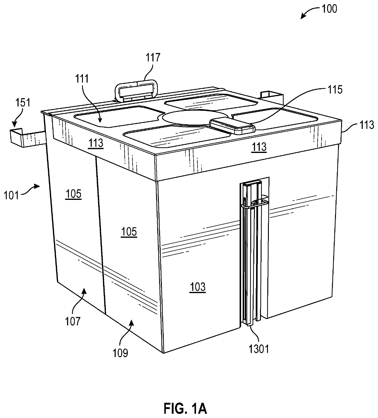
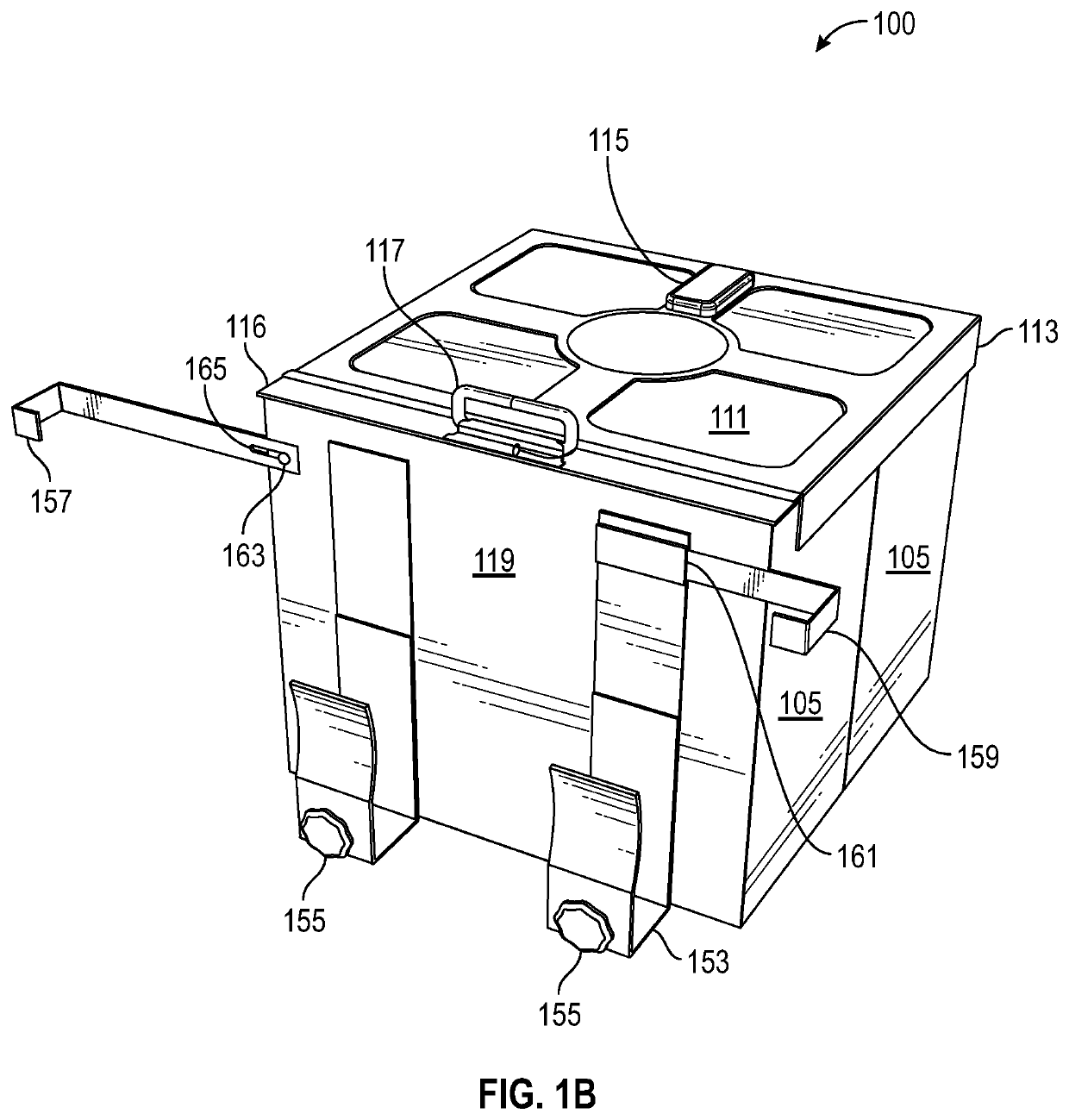
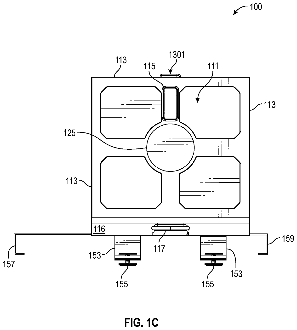
[0338]Note “PRL” as used herein may refer to “package-receiving-locker” as package-receiving-locker 100 or package-receiving-locker 900.

[0339]Note “SBL” as used herein may refer to “smart-box-locker” and may refer to package-receiving-locker 100 or package-receiving-locker 900. That is, “PRL” and “SBL” may be used interchangeably.

[0340]Note “PRL,”“package-receiving-locker,”“package-receiving-locker 100,” and “package-receiving-locker 900” should not be construed as being only applicable to packages. For example, and without limiting the scope of the present invention, “PRL,”“package-receiving-locker,”“SBL,”“smart-box-locker,”“package-receiving-locker 100,” and “package-receiving-locker 900” may removably hold, store, and / or store one or more: objects, packages, parcels, mail, boxes, containers, articles, documents, bags, sacks, pouches, consumer goods, electronic devices, clothing, food, beverages, and / or the like.

[0341]Note “PRL,”“package-receiving-locker,”“package-receiving-locker...


PUM


Abstract

Package-receiving-lockers (PRLs) may have a collapsible-locker portion and door-attachment-structure. PRLs may exist in a substantially collapsed configuration for storing the given PRL or for otherwise minimizing a footprint of the given PRL; and these PRLs may exist in a substantially deployed (expanded) configuration for acting as a secure object storage location. Regardless of configuration (deployed or collapsed), PRLs may be removably attached to side-hinged-doors with the door-attachment-structure, in such a way so as not to impair operation of the given door. The PRLs may have various electronics for facilitating access (e.g., locking and unlocking the collapsible-locker), delivery confirmation, and mitigating theft. These electronics, along with specialized software, may allow an intended recipient (e.g., a buyer), a shipper / delivery person (or shipping / deliver robot), and / or a seller / vendor to access the PRL in a controlled and documented manner. At least some of these electronics may be in wireless communications with other electronic devices.

Description

PRIORITY NOTICE[0001]The present application claims priority under 35 U.S.C. § 119(e) to U.S. Provisional Patent Application Ser. No. 62 / 673,070 filed on May 17, 2018, the disclosure of which is incorporated herein by reference in its entirety.[0002]The present application claims priority under 35 U.S.C. § 119(e) to U.S. Provisional Patent Application Ser. No. 62 / 796,805 filed on Jan. 25, 2019, the disclosure of which is incorporated herein by reference in its entirety.CROSS REFERENCE TO RELATED PATENT APPLICATIONS[0003]The present application makes no reference to any other related filed patent applications.STATEMENT REGARDING FEDERAL SPONSORSHIP[0004]No part of this invention was a result of any federally sponsored research.TECHNICAL FIELD OF THE INVENTION[0005]The present invention relates in general to collapsible lockers and more specifically to collapsible lockers that may be attached to or located proximate to a door; and / or wherein such door mountable collapsible lockers may...

Claims


Application Information

Patent Timeline
Patent Type & Authority Applications(United States)
IPC IPC(8): A47G29/14
CPCA47G29/141A47G2029/145A47G2029/144A47G2029/149A47G29/20
Inventor RAPHAEL, CARLOSORREGO, DANIELALTMAN, JASON SCOTTHARLAN, JEFFHARVEY, MICHAEL D.
Owner SECURUM CAPSA INC
Learn More