
Power steering system for a vehicle

a technology for power steering and vehicles, applied in the direction of electric steering, fluid steering, vehicle components, etc., can solve the problems of requiring space, heavy packaging work, and a large amount of pans, and achieve the effects of low consumption, high steering assistance, and low steering assistan

Active Publication Date: 2018-03-27
VOLVO LASTVAGNAR AB
View PDF15 Cites 3 Cited by
  • Summary
  • Abstract
  • Description
  • Claims
  • Application Information

AI Technical Summary

Benefits of technology

The power steering system in this patent helps drivers of vehicles to turn more easily by adding a force to the wheels through a steering actuator. This system may also include disconnecting means to prevent failure or to save energy. The disconnection can be done for safety or when the vehicle doesn't need additional steering assistance.

Problems solved by technology

However, a significant drawback of such a conventional power steering system is that it comprises heavy pans, and that it requires space—while the corresponding allotted space is generally limited.
Therefore, the implementation of such a system leads to heavy packaging work and involves some limitations due to the size of the wheels and / or of the vehicle frame.
Downsizing the first actuator also results in downsizing the mechanical arrangement connecting the steering gear and the steered wheel, in particular the drag link.
Besides, the impact of the second actuator on the system overall size is fairly low.

Method used


Image

  • Power steering system for a vehicle
  • Power steering system for a vehicle
  • Power steering system for a vehicle

Examples


first embodiment

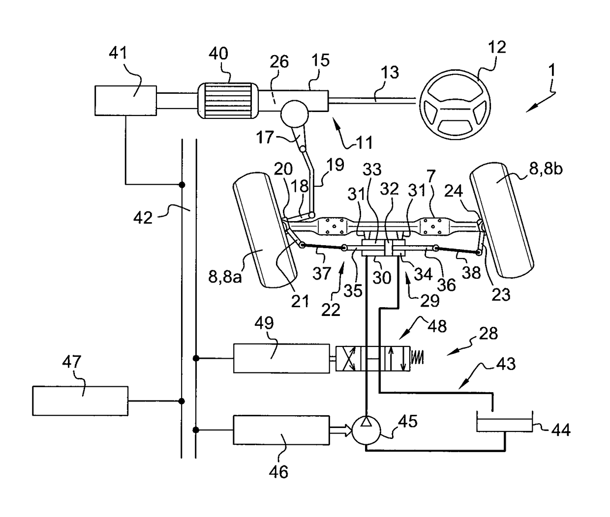
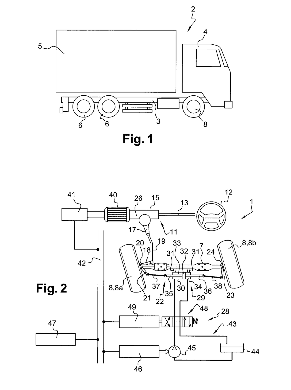
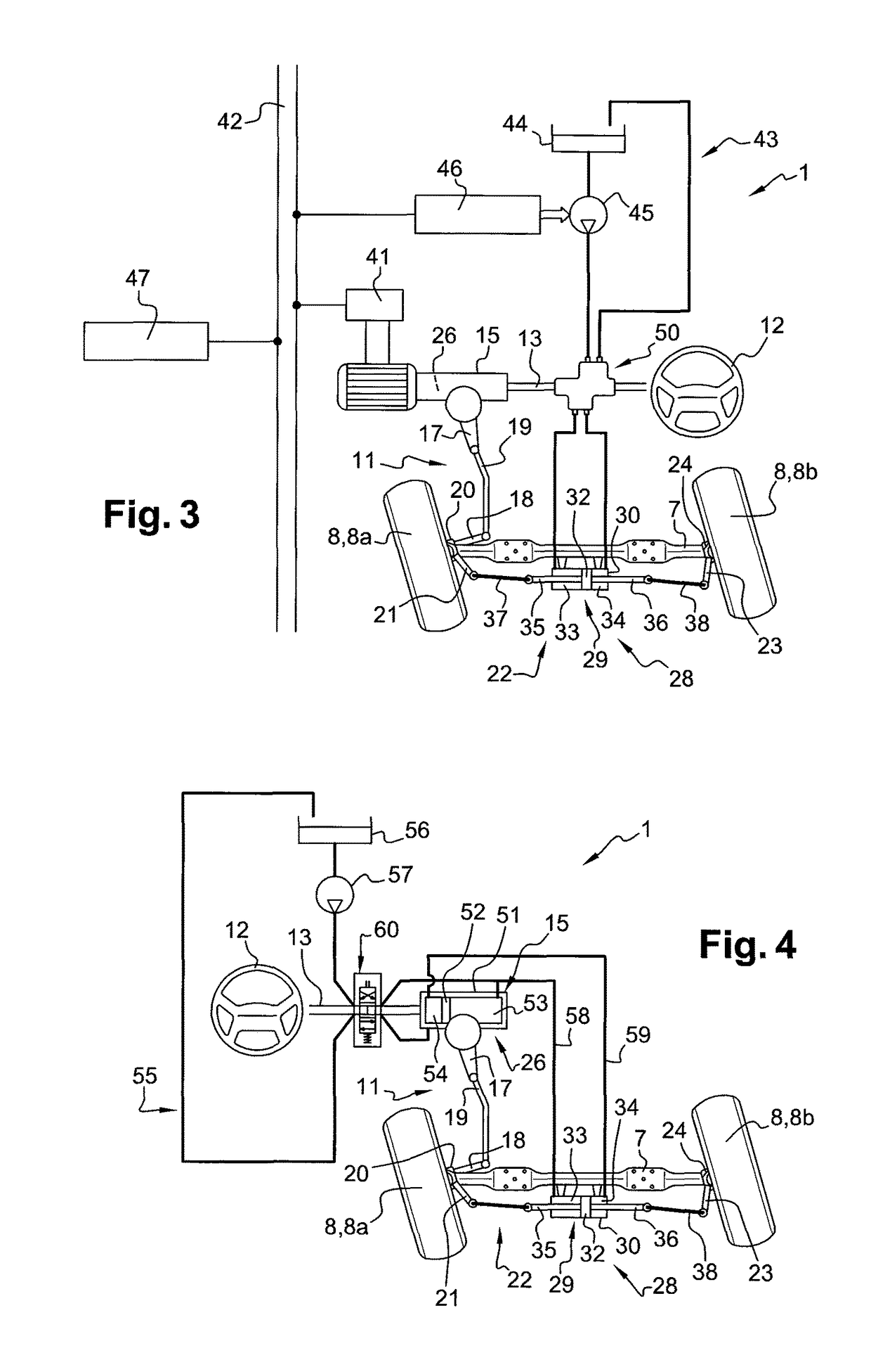
[0063]According to an aspect of the invention, depicted in FIGS. 2 and 3, the first actuator 26 is an electric actuator, i.e. an actuator powered by electric energy. A motor 40 is therefore coupled to the first actuator 26, generally close to the steering gear 15, to power said first actuator 26. The motor 40 is controlled by a motor control unit 41 connected to a communication bus 42, such as a CAN bus.

[0064]The second steering mechanism 28 comprises a hydraulic circuit 43 including the second actuator 29. Said hydraulic circuit 43 can typically comprise a tank 44 and a pump 45 which can be powered by a mechanical power source 46 controlled via the communication bus 42 by an electronic control unit 47.

[0065]In the variant of FIG. 2, the second steering mechanism 28 further comprises a valve 48 arranged in the hydraulic circuit 43 and which can be switched between three positions by means of a valve control unit 49 connected to the communication bus 42. In a first position, i.e. the...

second embodiment

[0067]According to an aspect of the invention, depicted in FIGS. 4 to 6, the first actuator 26 is a hydraulic actuator. It can typically comprise a cylinder barrel 51 in which a piston 52 can slide, the piston 52 defining inside the cylinder barrel 51 a first chamber 53 and a second chamber 54. A hydraulic circuit 55 including a tank 56 and a pump 57 makes it possible to direct hydraulic fluid in one of the two chambers 53, 54 depending on the action exerted by the driver on the steering wheel 12, in order to provide a steering assistance.

[0068]In the illustrated implementations, the second actuator 29 is hydraulically coupled to the first actuator 26. In practice, the hydraulic circuit 55 comprises a first conduit 58 between the first chambers 53, 33 of the first and second actuators 26, 29, and a second conduit 59 between the second chambers 54, 34 of the first and second actuators 26, 29. As a result, the pressures in the chambers 33, 34 of the second actuator 29 are substantiall...


PUM


Abstract

A power steering system includes a first steering mechanism designed to control the steering of at least one of the wheels of a steered axle and includes a mechanical transmission of the movement from a steering wheel of the vehicle to the wheel, a first actuator controlled by a parameter related to the steering wheel movement and capable of providing a steering assistance effort to the wheel. The power steering system further includes a second steering mechanism which includes a second actuator capable of providing a steering assistance effort to at least one of the wheels of the same axle, the second actuator having a housing which is secured to the axle, a first and a second piston rods able to slide through the housing and extending, on opposite sides, beyond the housing, with the piston rods being substantially parallel to the axle.

Description

BACKGROUND AND SUMMARY[0001]The present invention relates to a power steering system for a vehicle, especially an industrial vehicle such as a heavy truck.[0002]A power steering system has been a standard feature in vehicles for many years, in particular in industrial vehicles. Such a system assists the vehicle driver by applying a force to the wheels, through a steering actuator, which complements the effort of the driver which is mechanically transmitted from the steering wheel to the steered wheels of the vehicle. Therefore, a lower effort is required for the driver when turning the steering wheel and the vehicle is easier to manoeuvre.[0003]Typically, a power steering system comprises a steering gear including the actuator capable of providing a steering assistance effort to at least one of the wheels of the axle. This actuator is controlled by a parameter related to the steering wheel movement, for example as a function of the steering effort exerted by the driver on the steeri...

Claims


Application Information

Patent Timeline
Patent Type & Authority Patents(United States)
IPC IPC(8): B62D5/06B62D5/08B62D6/02B62D5/04B62D5/065B62D5/12
CPCB62D5/04B62D5/0409B62D6/02B62D5/08B62D5/12B62D5/06B62D5/065
Inventor BLOND, JEAN-MARC
Owner VOLVO LASTVAGNAR AB
Learn More