
Knee protecting air bag system

a technology for air bags and knees, which is applied in the direction of pedestrian/occupant safety arrangements, vehicular safety arrangements, vehicle components, etc., can solve the problem that the air bag cannot enter the narrow space defined between the knees of the occupant and the body side member, and achieves the effect of preventing the air bag from slipping and falling o

Active Publication Date: 2018-10-09
TOYODA GOSEI CO LTD
View PDF23 Cites 3 Cited by
  • Summary
  • Abstract
  • Description
  • Claims
  • Application Information

AI Technical Summary

Benefits of technology

The patent describes an air bag system that can protect the knees of a car occupant during a collision. The system includes an air bag that is mounted in the vehicle's body side member and inflates along the rear surface of the vehicle's body side member to a maximum extent. The upper inflating portion of the air bag rises along the rear surface of the body side member to a maximum extent and can easily enter the space between the occupant's knees and the vehicle's body side member. The system also ensures that the upper inflating portion deploys quickly to protect the occupant's knees in case of a collision. The system is designed to be effective even in narrow spaces between the vehicle's body side member and the knees of the occupant.

Problems solved by technology

In the conventional knee protecting air bag system, however, when the upper inflating portion of the air bag deploys to inflate upwards from the housing portion as a result of the air bag system being activated, although the thickness of the air bag is controlled by the tethers, in case the air bag deploys to inflate while being spaced apart to the rear from the body side member, the air bag has difficulty in entering a narrow space defined between the knees of the occupant and the body side member.

Method used


Image

  • Knee protecting air bag system
  • Knee protecting air bag system
  • Knee protecting air bag system

Examples


Embodiment Construction

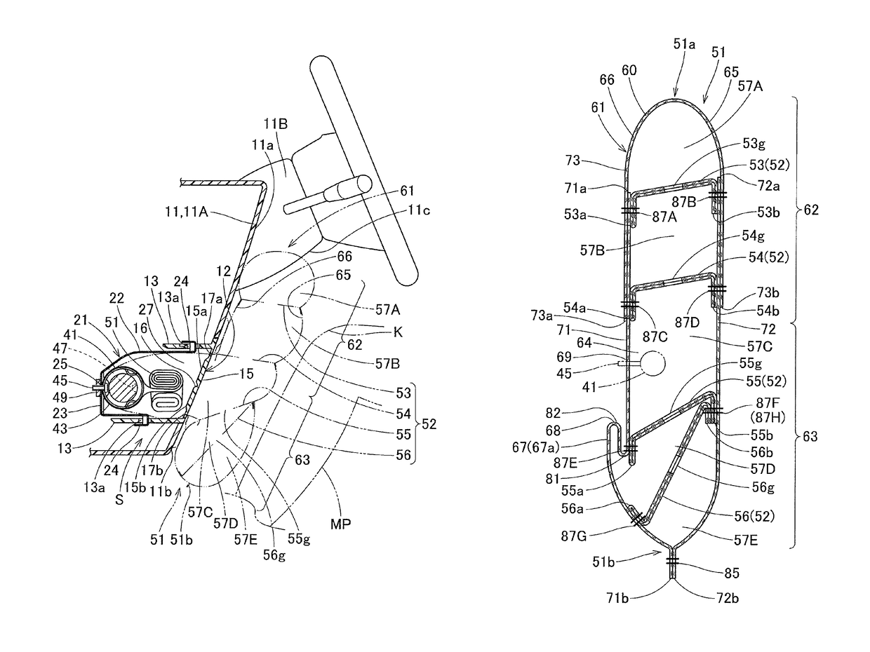
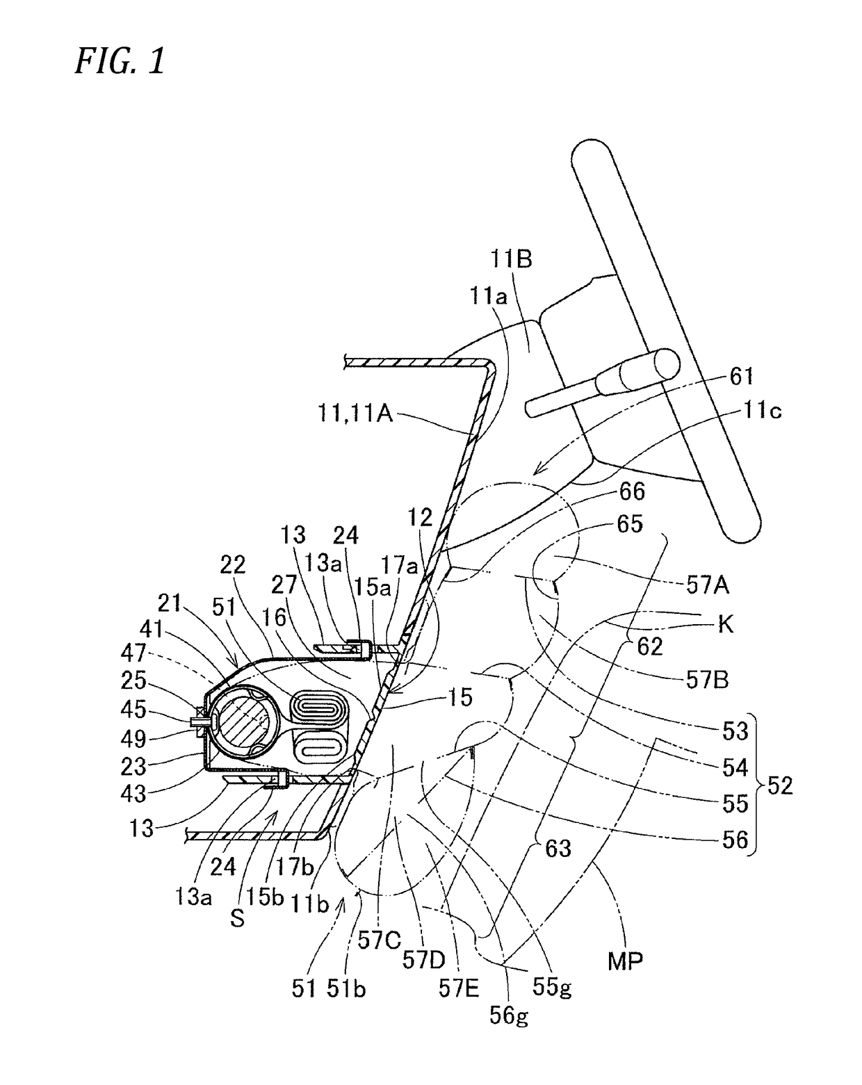
[0037]Hereinafter, an embodiment of the invention will be described based on the drawings. In the embodiment, as shown in FIG. 1, a knee protecting air bag system S will be described as being disposed in front of a driver's seat.

[0038]As shown in FIG. 1, the knee protecting air bag system S of this embodiment is disposed on a lower side 11b of an instrument panel 11A that is a body side member 11 disposed in front of the driver's seat, and a column cover 11B is disposed on an upper side 11a of the instrument panel 11A. The knee protecting air bag system S includes a folded air bag 51, an inflator 41 that supplies the air bag 51 with inflation gas, a case 21 as a housing portion where the folded air bag 51 and the inflator 41 are housed, and an air bag cover 12 that covers an air bag projecting opening 27 of the case 21.

[0039]When referred to in this specification, unless otherwise described, an up-to-down direction, a left-to-right direction and a front-to-rear direction coincide wi...


PUM


Abstract

A knee protecting air bag system includes an air bag, folded to be housed in a housing portion on a lower side of a body side member in front of a seated occupant. The air bag includes thickness controlling tethers that are provided so as to connect an occupant side wall portion and a body side wall portion when the air bag inflates completely. The thickness controlling tethers include an upper tether and a lower tether that are provided to extend into a belt-like shape along a left-to-right direction in upper and lower positions in the lower inflating portion when the air bag inflates completely. An abutment portion is formed between a portion where the upper tether is connected to the body side wall portion and a portion where the lower tether is connected to the body side wall portion.

Description

CROSS-REFERENCE TO RELATED APPLICATION(S)[0001]This application is based upon and claims the benefit of priority from Japanese Patent Application No. 2015-171302, filed on Aug. 31, 2015, the entire contents of which are incorporated herein by reference.BACKGROUND[0002]1. Field of the Invention[0003]The present invention relates to a knee protecting air bag system in which an air bag housed on a lower side of a body side member such as an instrument panel is inflated so as to protect the knees of an occupant.[0004]2. Description of the Related Art[0005]A conventional knee protecting air bag system includes an air bag that is folded to be housed in a housing portion on a lower side of a body side member such as an instrument panel that lies in front of an occupant seated in a driver's or a front passenger's seat (for example, refer to JP-A-2002-337642 and JP-A-2005-75143). As portions that deploy to inflate towards the rear from the housing portion by introducing inflation gas therein...

Claims


Application Information

Patent Timeline
Patent Type & Authority Patents(United States)
IPC IPC(8): B60R21/206B60R21/231B60R21/233B60R21/2338
CPCB60R21/206B60R21/231B60R21/233B60R21/2338B60R2021/23382B60R2021/23169B60R2021/23324
Inventor ANDO, TAKESHI
Owner TOYODA GOSEI CO LTD
Learn More