Band connecting device and head mounted display including the same

a technology of connecting device and display device, which is applied in the direction of instruments, details of portable computers, computing, etc., can solve the problems of increasing the weight applied to the facial side of the wearer, and uncomfortable wearing feeling

a technology of connecting device and display device, which is applied in the direction of instruments, details of portable computers, computing, etc., can solve the problems of increasing the weight applied to the facial side of the wearer, and uncomfortable wearing feeling

US10095275B2Active Publication Date: 2018-10-09SAMSUNG ELECTRONICS CO LTD

Image

  • Band connecting device and head mounted display including the same
  • Band connecting device and head mounted display including the same
  • Band connecting device and head mounted display including the same

Examples


Embodiment Construction

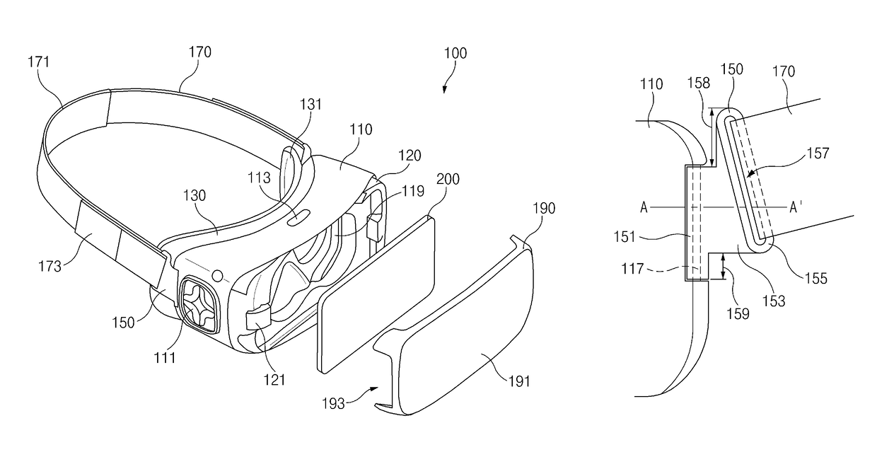
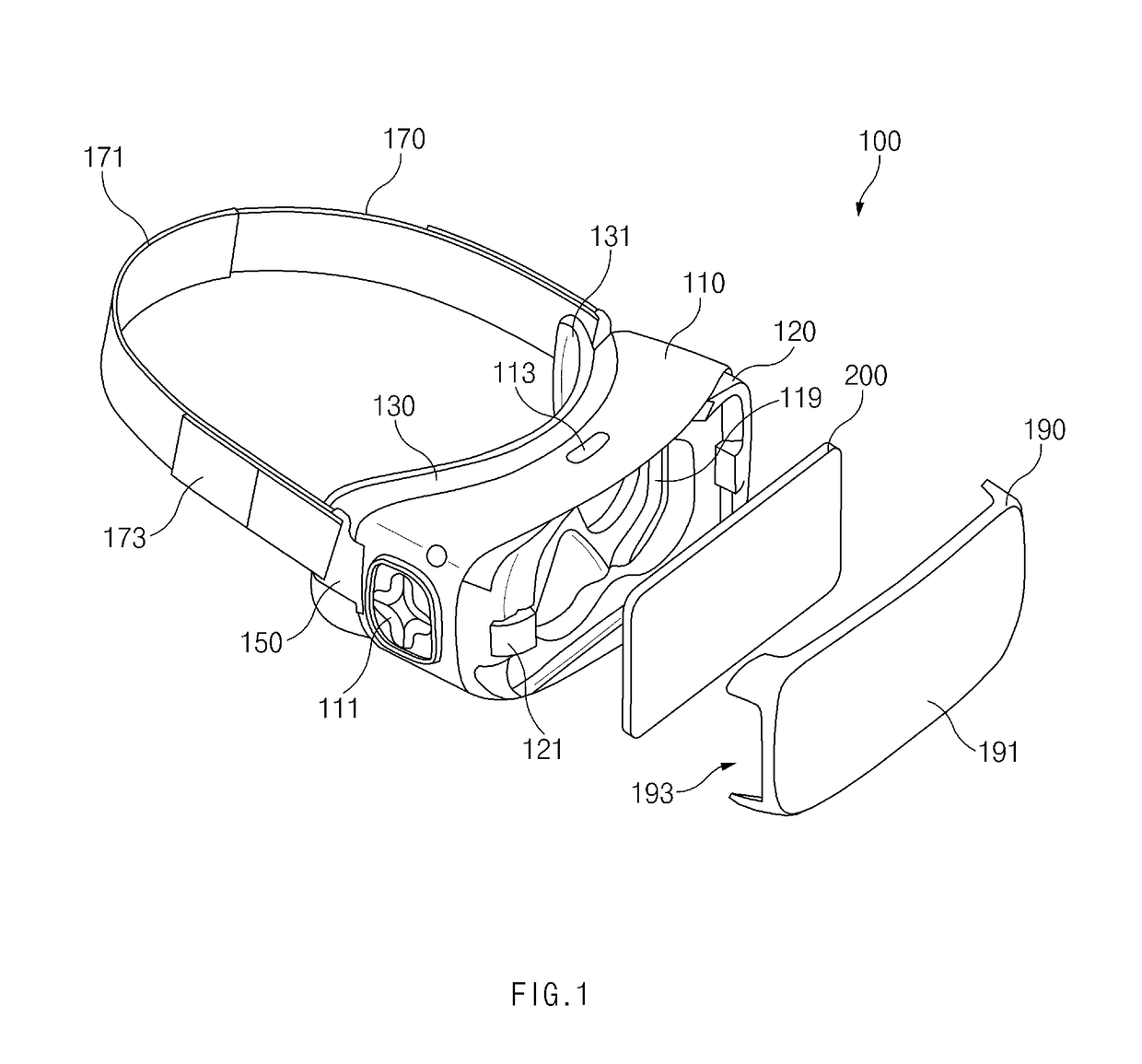
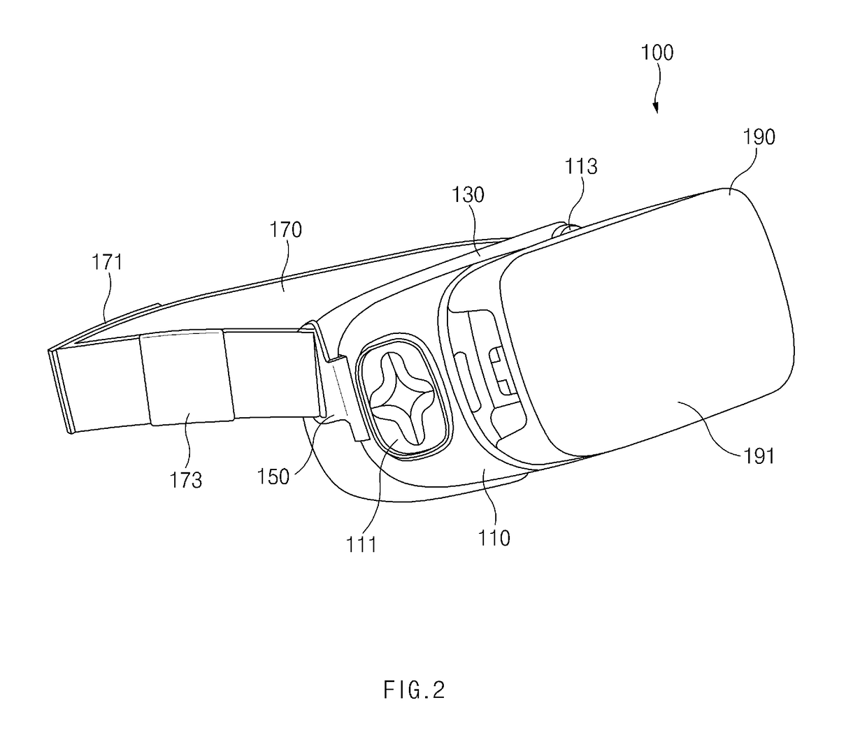
[0037]Hereinafter, various embodiments of the present disclosure are disclosed with reference to the accompanying drawings. However, the present disclosure is not intended to be limited by the various embodiments described herein and it is intended that the present disclosure covers all modifications, equivalents, and / or alternatives of the present disclosure provided they come within the scope of the appended claims and their equivalents.

[0038]With respect to the descriptions of the accompanying drawings, like reference numerals refer to like elements.

[0039]All terms used herein may have the same meanings that are generally understood by a person skilled in the art. In general, terms defined in a dictionary should be considered to have the same meanings as the contextual meanings of the related art, and unless clearly defined as such herein, should not be understood differently or as having an excessively formal meaning. In any case, even terms defined in the present specification ...


PUM


Abstract

A head mounted display device is provided. A head mounted display device includes a main frame including surface formed to face a facial side of a user and an opposite surface on which an external electronic device is mounted; a connecting device connected to the main frame; and a support part connected to the connecting device that fixes the head mounted display device to the facial side of the user. At least a portion of a surface of the connecting device, which is connected to the support part, forms an angle with a direction in which the main frame faces the facial side of the user.

Description

PRIORITY[0001]This application claims priority under 35 U.S.C. ยง 119(a) to Korean Patent Application Serial No. 10-2015-0136843, which was filed in the Korean Intellectual Property Office on Sep. 25, 2015, the entire disclosure of which is incorporated herein by reference.BACKGROUND[0002]1. Field of the Disclosure[0003]The present disclosure relates generally to a band connecting device, and more particularly, to a head mounted display device including the band connecting device.[0004]2. Related Art[0005]Wearable electronic devices that may be directly mounted (e.g., worn) on the human body are available. Because these wearable electronic devices may be mounted on a portion of the human body, e.g., a wrist, an ankle, the neck, the waist, or the head of the user, mobility and portability can be improved. For example, a head mounted display (HMD) device is worn on the head of the user to display an image and may include a support part, such as a band, to hold the HMD on the head of th...

Claims


Application Information

Patent Timeline
09 Oct 2018
Publication
US10095275B2
IPC
G09G5/00; G06F1/16; G06T19/00
CPC
G06F1/166; G06F1/163; G06F1/1681; G06F1/169; G06T19/006; G06F1/1686; G06F1/1694; G06F1/1698
Inventors
BYUN, DONG HYUN; PARK, JOONG KYUNG