An automated lifting fixture

A fixture and hoisting technology, which is applied in the field of automatic hoisting fixtures, can solve problems such as unstable clamping, small contact area, and easy sliding, and achieve the effect of stable suspension and increased contact area

Active Publication Date: 2022-04-08
付安英
View PDF5 Cites 0 Cited by
  • Summary
  • Abstract
  • Description
  • Claims
  • Application Information

AI Technical Summary

Problems solved by technology

[0002] The lifting of large cylindrical or barreled objects is generally fixed at the bottom, and then lifted by the hook, which makes the process of clamping the entire cylindrical object more time-consuming
[0003] The existing clamps usually use the traditional clip set as an arc, which is clamped from both symmetrical sides to form a way to hold and clamp the barrel body. Due to the small contact area, when the entire barrel is too heavy It is easy to slide down, and this method is also used for the variable diameter barrel with the upper diameter larger than the lower diameter, resulting in poor overall clamping effect and easy clamping instability

Method used


Image

  • An automated lifting fixture
  • An automated lifting fixture
  • An automated lifting fixture

Examples


Embodiment Construction

[0024] In order to enable those skilled in the art to better understand the technical solutions of the present invention, the present invention will be described more clearly and completely below in conjunction with the accompanying drawings in the embodiments. Of course, the described embodiments are only a part of the present invention. Not all, based on this embodiment, other embodiments obtained by those skilled in the art without creative efforts are all within the protection scope of the present invention.

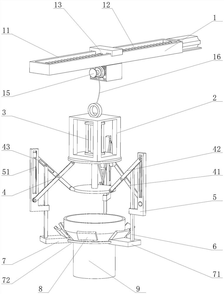
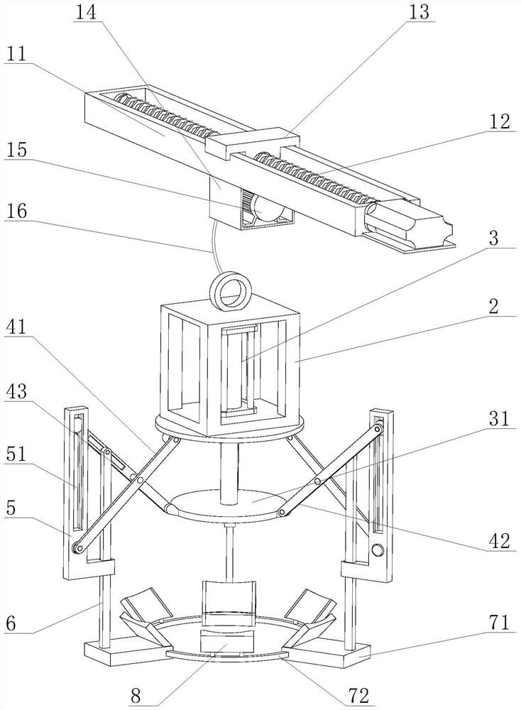
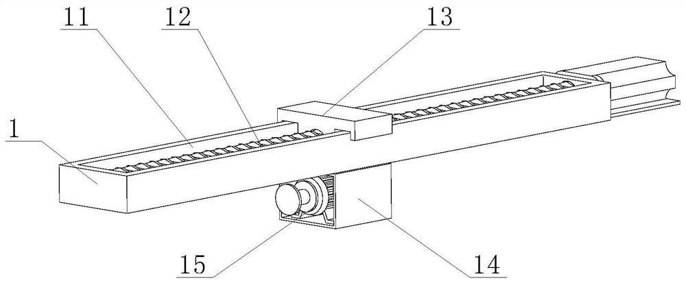
[0025] Such as Figure 1-Figure 6 As shown, an automatic lifting fixture includes a lifting part 1 for hoisting and a clamping part suspended below the lifting part 1 for clamping the barrel body 9. The clamping part drives the shears through the built-in hydraulic cylinder 3. One end of the fork 4 is opened and closed, and the position of the L-shaped plate 5 and the straight bar 6 at the other end of the scissors 4 is controlled.

[0026] The clamping part include...


PUM


Abstract

The invention relates to an automatic hoisting fixture, which includes a hoisting part for hoisting and a clamping part suspended below the hoisting part for clamping a barrel, and the clamping part drives the shears through a built-in hydraulic cylinder. One end of the fork is opened and closed to control the position change of the L-shaped plate and the straight rod at the other end of the scissors. The position change of the straight rod drives the fixedly connected telescopic ring to expand and contract to fix the barrel. In the present invention, three circularly distributed scissors are controlled by a hydraulic cylinder to expand and contract synchronously. The first plate of the scissors drives the L-shaped plate to move, and the L-shaped plate and the second plate of the scissors jointly define a straight bar. The direction of movement makes the straight rod move inward and upward when clamping, driving the fixedly connected telescopic ring to close and clamp while the telescopic ring moves up, driving the diagonal brace on the telescopic ring to move to the diameter of the outer wall of the barrel Change the transitional part for fitting support and clamping.

Description

technical field [0001] The invention relates to the field of fixtures, in particular to an automatic lifting fixture. Background technique [0002] The hoisting of large cylindrical or barreled objects is generally carried out after being fixed at the bottom, and then lifted by the hook, which makes the process of clamping the entire cylindrical object more time-consuming. [0003] The existing clamps usually use the traditional clip set as an arc, which is clamped from both symmetrical sides to form a way to hold and clamp the barrel body. Due to the small contact area, when the entire barrel is too heavy It is easy to slide down, and this method is also used for the variable diameter barrel whose upper diameter is larger than the lower diameter, resulting in poor overall clamping effect and easy to cause clamping instability. Contents of the invention [0004] Now in order to meet the above-mentioned requirements for adapting and clamping the variable-diameter barrel wh...

Claims


Application Information

Patent Timeline
Patent Type & Authority Patents(China)
IPC IPC(8): B66C1/42
CPCB66C1/422
Inventor 付安英
Owner 付安英
Why Eureka
Try Eureka