Supercharge Your Innovation With Domain-Expert AI Agents!

Uninterruptible power source device

a power source device and uninterruptible technology, applied in the direction of emergency power supply arrangements, electric vehicles, transportation and packaging, etc., can solve the problems of uninterruptible power source devices, the inability of alkaline secondary batteries to charge to full-charge state, etc., and achieve the effect of small electric power loss and higher reliability

Active Publication Date: 2018-10-09
FDK CORP
View PDF23 Cites 0 Cited by
  • Summary
  • Abstract
  • Description
  • Claims
  • Application Information

AI Technical Summary

Benefits of technology

[0018]According to the present invention, it is possible to provide an uninterruptible power source device with a smaller electric power loss and a higher reliability.

Problems solved by technology

An uninterruptible power source device is a power source device that supplies electric power from a previously charged secondary battery to a loading device for continuing the operation of the loading device, in a state in which electric power is not supplied from an external power source to the loading device due to electric power interruption or the like.
However, generally, in the uninterruptible power source device, the rated voltage of the alkaline secondary battery is the same as the voltage of the external power source.
Therefore, at that voltage, the alkaline secondary battery cannot be charged to a full-charge state, with the electric power of the external power source.
For this reason, there is publicly known an uninterruptible power source device including an auxiliary power source (DC / DC converter) that raises the voltage of the external power source.
Further, although not an uninterruptible power source device, as an example of the technology that uses the auxiliary power source, there is publicly known a motor control device to increase, by the auxiliary power source, the amount of the electric power that can be supplied to an electric motor, when the electric power demand of the electric motor increases temporarily (see Patent Document 1, for example).

Method used


Image

  • Uninterruptible power source device
  • Uninterruptible power source device
  • Uninterruptible power source device

Examples


Embodiment Construction

[0024]Hereinafter, embodiments of the present invention will be described with reference to the drawings.

[0025]Needless to say, the present invention is not particularly limited to the embodiments described below, and various modifications can be made within the range of the invention described in CLAIMS.

10>

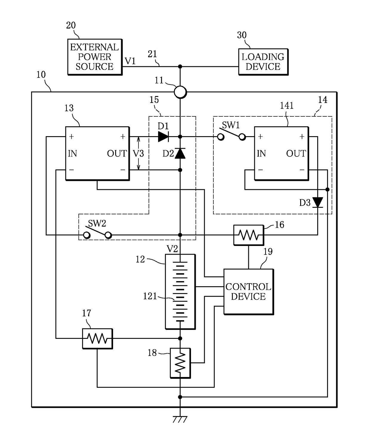
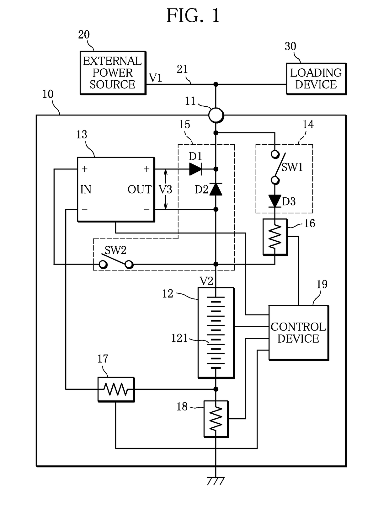
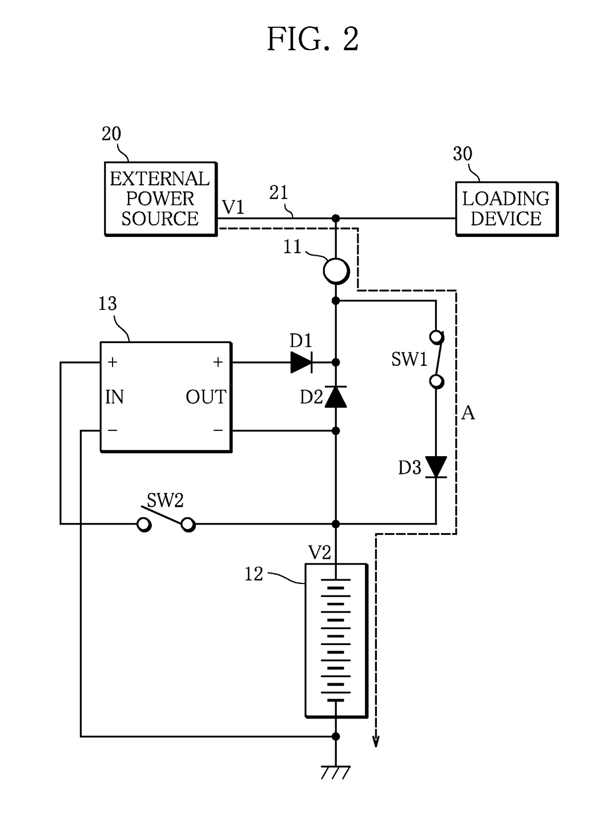
[0026]The configuration of an uninterruptible power source device 10 according to the present invention will be described with reference to FIG. 1.

[0027]FIG. 1 is a circuit diagram illustrating the configuration of the uninterruptible power source device 10.

[0028]The uninterruptible power source device 10 is a power source device that supplies electric power to a loading device 30 for continuing the operation of the loading device 30, in a state in which electric power cannot be supplied from an external power source 20 to the loading device 30 due to electric power interruption or the like.

[0029]The uninterruptible power source device 10 includes an input-output terminal 11, a b...


PUM


Abstract

An uninterruptible power source device 10 in the present invention includes: an input-output terminal 11 that is connected in parallel with a power source line 21 through which electric power is supplied from an external power source 20 to a loading device 30; a battery unit 12 whose rated voltage is lower than a voltage V1 of the external power source 20; a DC / DC converter 13 that converts a voltage V2 of the battery unit 12 into a voltage V3 equivalent to a difference between the voltage V1 of the external power source 20 and the voltage V2 of the battery unit 12; a charging circuit 14 that charges the battery unit 12 through the input-output terminal 11 with the electric power of the external power source 20; and a discharging circuit 15 that performs discharge to the loading device 30 through the input-output terminal 11 at a voltage resulting from adding an output voltage V3 of the DC / DC converter 13 to the voltage V2 of the battery unit 12, at the time of electric power interruption of the external power source 20.

Description

TECHNICAL FIELD[0001]The present invention relates to an uninterruptible power source device.BACKGROUND ART[0002]An uninterruptible power source device is a power source device that supplies electric power from a previously charged secondary battery to a loading device for continuing the operation of the loading device, in a state in which electric power is not supplied from an external power source to the loading device due to electric power interruption or the like. The secondary battery of the uninterruptible power source device is generally charged with the electric power of the external power source, at normal times. As an example of the secondary battery that is used in the uninterruptible power source device, an alkaline secondary battery such as a nickel-hydrogen secondary battery is publicly known, for example.[0003]The alkaline secondary battery, from its nature, needs to be charged at a voltage that is higher than the rated voltage. However, generally, in the uninterrupti...

Claims


Application Information

Patent Timeline
Patent Type & Authority Patents(United States)
IPC IPC(8): H02J9/06H02J7/00
CPCH02J7/0068H02J9/061H02J2207/20
Inventor HARADA, TAKUYAKABASAWA, TAKASHISAKAMOTO, JINICHI
Owner FDK CORP
Features
  • R&D
  • Intellectual Property
  • Life Sciences
  • Materials
  • Tech Scout
  • Unparalleled Data Quality
  • Higher Quality Content
  • 60% Fewer Hallucinations
Learn More