Check patentability & draft patents in minutes with Patsnap Eureka AI!

Fuel cell

a fuel cell and cell technology, applied in the field of fuel cells, can solve the problems of reducing the characteristic of the electrode, requiring a great deal of starting time, and low heating efficiency, and achieve the effect of low heating efficiency

Inactive Publication Date: 2007-01-02
NISSAN MOTOR CO LTD
View PDF25 Cites 3 Cited by
  • Summary
  • Abstract
  • Description
  • Claims
  • Application Information

AI Technical Summary

Benefits of technology

[0012]The present invention was made with the foregoing problems of the conventional fuel cell in mind. It is an object of the present invention to provide a fuel cell capable of quickly and homogeneously heating a power generation layer portion of the fuel cell up to a temperature of generating power, improving starting performance, generating power at a high output density with a small electric power loss immediately after starting of power generation, and preventing damage by a thermal shock to improve durability.

Problems solved by technology

However, in the case of the flat-plate stack described in each of the foregoing publications, because of no heating means provided as described above, the entire stack is heated by a heating device installed outside of the stack at starting time.
Thus, heating efficiency is low, requiring a great deal of starting time.
Moreover, in the case of the cylindrical stack described in the paper of Journal of Power Sources, since the cell functions as a fuel cylinder at starting time, an electrode layer formed on an inner or outer wall of the cell is damaged or oxidized, causing a problem of a reduction in an electrode characteristic.
Furthermore, in the method described in the article of the above-described 45th SOFC workshop, because of a cylindrical shape of the combustion cylinder, a cell heating degree varies from position to position, and even one cell is difficult to be heated homogeneously.
Therefore, thermal stress is apt to be applied to the cell, causing damage.
If there is variance in output electric power among the cells, a problem occurs, i.e., a great loss of the output electric power of the entire stack.
For example, if temperatures are different among parts of the plurality of cells electrically connected in parallel, and a cell generating a small electric power voltage or a cell of a large internal resistance is connected, not only electric power generated by the cell cannot be taken out, but also power generated by a high output electric power cell is consumed inside, or heat is generated locally, causing a great loss.

Method used


Image

  • Fuel cell
  • Fuel cell
  • Fuel cell

Examples


first example

(a) Combustion Heater Plate

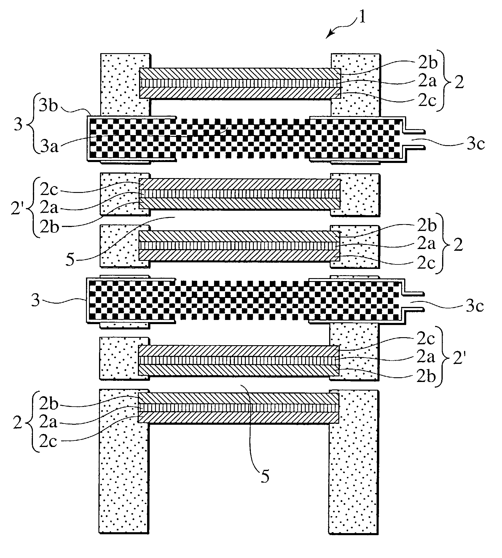
[0059]As a porous combustion support 3a, metal felt made of Fe—Cr—Al containing heat-resisting steel and having a thickness of 2 mm is used. A full surface of the combustion support 3a was covered with a thin plate (i.e., gas non-pass layer 3b) made of heat-resisting steel, and supply and exhaust ports 3c and 3e for heating gas were formed on parts of a side face. Thus, a combustion heater plate 3 as shown in FIG. 1 was obtained. In this time, as in the case of a normal separator, a material layer identical to an electrode material of an opposite cell plate can be formed on the gas non-pass layer 3b for control of a passage, and an increase of a heating area.

(b) Cell Plate (Air Electrode Supporting Type)

[0060]First, a solvent and a binder were added to lanthanum strontium manganate LaSrMnO3 (abbreviated to LSM, hereinafter) powder having a mean diameter of particles 3 to 10 μm, and mixed. This mixture was formed in a plate shape by extrusion molding. By si...

second example

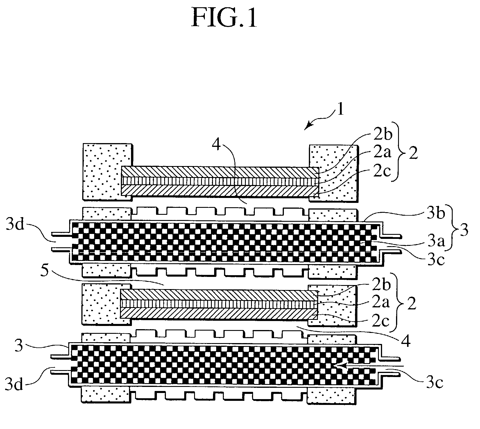
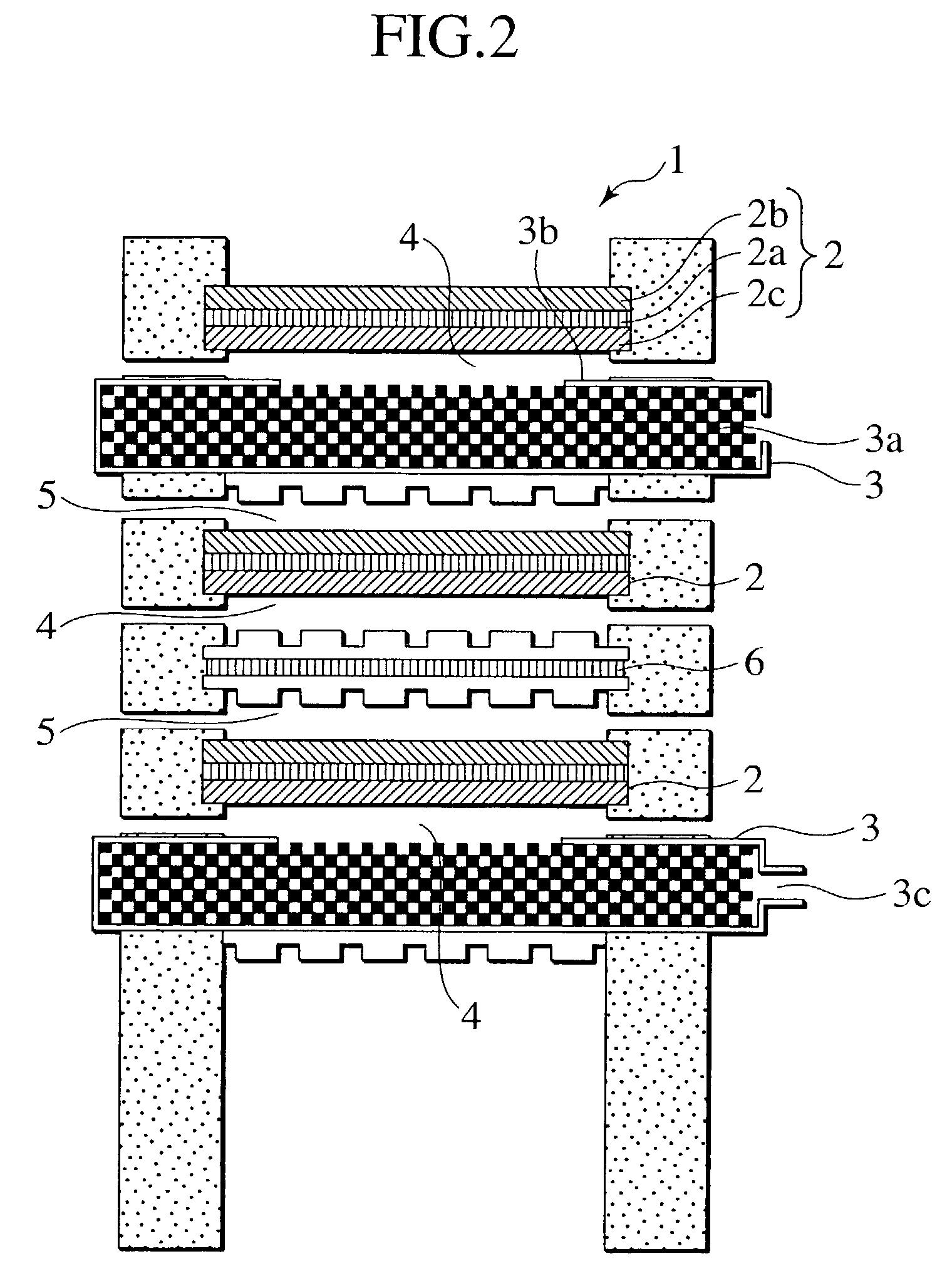
[0064]A cell plate 2 similar to that in the first example was used. Further, a combustion heater plate 3 of a type having a structure basically similar to that of the combustion heater plate 3 shown in the first example, in which no gas non-pass layers 3b are formed on a surface opposite the cell plate 2, was used. Also, a separator 6 having passages of fuel and air electrode materials formed on both surfaces of a lanthanum-chrome containing oxide plate was used. As shown in FIG. 2, one separator out of every two separators in a normal stack formed by alternately laminating cell plates and the separators was substituted with a combustion heater plate 3. Accordingly, a fuel cell stack 1 was formed by including four cell plates 2, two combustion heater plates 3, and three separators 6 (separator 6, cell plate 2, combustion heater plate 3, cell plate 2, separator 6, cell plate 2, combustion heater plate 3, cell plate 2, and separator 6). Moreover, as in the case of the first example, t...

third example

[0066]A cell plate 2 similar to that in the first example was used. For a porous combustion support 3a, as in the case of a general exhaust gas processing catalyst converter, a cordierite honeycomb supporting Pt was used as a catalyst. A combustion heater plate 3 having no gas non-pass layers 3b formed on a surface opposite the cell plate 2 in the combustion support 3a was used. Except for use of the combustion heater plate 3 having such a characteristic, a fuel cell stack 1 having a laminated structure similar to that of the first example was obtained (refer to FIG. 3).

[0067]At starting time of the fuel cell, a mixed gas of fuel (propane gas) for heating and air was introduced from a gas supply port 3c of the combustion heater plate 3, thus heating the cell plate 2. After a temperature was increased to a predetermined temperature, an air-fuel ratio was reduced, and fuel gas for power generation (hydrogen) was supplied to a fuel passage 5, thus starting power generation. In the fuel...


PUM

PropertyMeasurementUnit
operating temperatureaaaaaaaaaa
thicknessaaaaaaaaaa
mean diameteraaaaaaaaaa

Abstract

A fuel cell of the present invention includes a fuel cell stack (1) for being formed by stacking a plurality of cell plates (2) having a flat shape, the cell plates (2) being configured by arranging a plurality of cells, the cell having an electrolyte layer (2a), a fuel electrode layer (2b) and an air electrode layer (2c). A combustion heater plate (3) includes a porous combustion plate (3a) and a gas non-pass layer (3b) covering a surface of the porous combustion plate (3a). The combustion heater plate (3) is disposed between the cell plates (2).

Description

BACKGROUND OF THE INVENTION[0001]1. Field of the Invention[0002]The present invention generally relates to a fuel cell such as a solid oxide fuel cell or the like which has an electrolyte, a fuel electrode and an air electrode, and which generates electric energy by electrochemical reaction, and more particularly to a fuel cell having a following feature: a combustion heater is incorporated in the fuel cell, thereby improving both the starting performance and restarting performance of the fuel cell.[0003]2. Description of the Related Art[0004]A fuel cell has a structure where a high-performance electrolyte for conducting an ion such as an oxygen ion (O2−), a proton (H+) or the like is held between a porous air electrode and a porous fuel electrode. Moreover, the fuel cell generates an electromotive force by respectively supplying oxidizing gas containing oxygen gas to the air electrode side and reducing gas containing hydrogen or hydrocarbon gas to the fuel electrode side, and elect...

Claims


Application Information

Patent Timeline
Patent Type & Authority Patents(United States)
IPC IPC(8): H01M8/04H01M8/02H01M8/12H01M8/24
CPCH01M8/0297H01M8/04022H01M8/243H01M8/2465H01M8/2425Y02E60/50H01M8/2432H01M8/0267
Inventor KUSHIBIKI, KEIKOHATANO, MASAHARUSHIBATA, ITARUFUKUZAWA, TATSUHIROHARA, NAOKISONG, DONGHISHITANI, YOSHIKOSATOU, FUMINORIUCHIYAMA, MAKOTOYAMANAKA, MITSUGU
Owner NISSAN MOTOR CO LTD
Features
  • R&D
  • Intellectual Property
  • Life Sciences
  • Materials
  • Tech Scout
  • Unparalleled Data Quality
  • Higher Quality Content
  • 60% Fewer Hallucinations
Learn More