Method and device for sending and receiving an optical signal

a technology of optical signals and methods, applied in the field of optical communication, can solve the problems of significant reduction of signal spectral efficiency (bit rate of transmission/bandwidth occupied by optical signals), poor mpq modulation format to improve signal transmission bit rate, and increase in transmission signal spectral efficiency, so as to reduce the spectral efficiency of transmission signals and save transmission bandwidth. , the effect of high power efficiency

Active Publication Date: 2018-10-09
BEIJING UNIV OF POSTS & TELECOMM
View PDF4 Cites 0 Cited by
  • Summary
  • Abstract
  • Description
  • Claims
  • Application Information

AI Technical Summary

Benefits of technology

[0006]The embodiments of the present application disclose a method and device for sending and receiving an optical signal, which are capable of decreasing spectral efficiency loss or even eliminating the same in optical communication while improving power efficiency. The specific technical solution is as follows:
[0064]In conclusion, in the method and device for sending and receiving an optical signal according to the embodiments of the present application, after a serial-to-parallel conversion is performed on a data signal to be transmitted, the obtained I path data sequence, Q path data sequence and PPM path data sequence which are in parallel are mPQ-encoded; after obtaining the I path and the Q path of an mPQ-encoded digital signal, different from the prior art in which the I path and the Q path of the mPQ-encoded digital signal are converted from digital to analog directly and then are mapped with an optical carrier, in the present application the I path and the Q path of the mPQ-encoded digital signal are shaped by Nyquist-filtering and the I path and Q path of the filtered digital signal are converted from digital to analog and then are mapped with the optical carrier. In the prior art, the method, in which the I path and the Q path of the mPQ-encoded digital signal are converted from digital to analog directly and then are mapped with an optical carrier, sacrifices a large amount of transmission bandwidth when obtaining a high power efficiency, resulting in a decrease in spectral efficiency of transmission signal. The method according to embodiments of the present application, in which the I path and the Q path of the mPQ-encoded digital signal are shaped by Nyquist-filtering, can effectively reduce transmission bandwidth of an optical signal and thereby achieve the purpose of decreasing or even eliminating loss in spectral efficiency while improving power efficiency.

Problems solved by technology

However, compared to QPSK, this method sacrifices a large amount of transmission bandwidth while achieving higher power efficiency, which directly results in a decrease in spectral efficiency of the transmission signal (spectral efficiency mainly refers to bit rate of transmission / bandwidth occupied by optical signals).
Furthermore, the ability of mPQ modulation format to improve the bit rate of signal transmission is poor, such that signal spectral efficiency (bit rate of transmission / bandwidth occupied by optical signals) is significantly decreased.
Under the condition that hardware equipment of the entire set transmission system is unchanged, transmission signal cannot exceed the maximum signal bandwidth which an electric equipment can meet, and then an mPQ signal with poorer spectral efficiency can only achieve lower transmission rate, which restricts transmission capacity.
Thus, how to decrease spectral efficiency loss or even eliminate spectral efficiency loss in optical communication while improving power efficiency is an urgent problem to be solved.

Method used


Image

  • Method and device for sending and receiving an optical signal
  • Method and device for sending and receiving an optical signal
  • Method and device for sending and receiving an optical signal

Examples


Embodiment Construction

[0074]The technical solutions in the embodiments of the present application will be clearly and completely described below in combination with the figures of the embodiments of the present application. Obviously, the described embodiments are only parts of the embodiments of the present application rather than all the embodiments thereof. Based on the embodiments of the present application, all the other embodiments obtained by those skilled in the art without creative efforts fall into the protection scope of the present application.

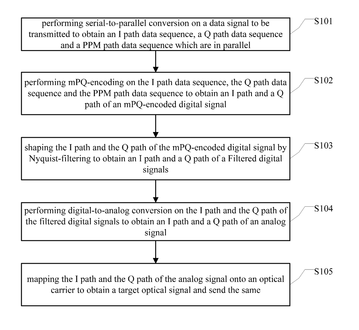
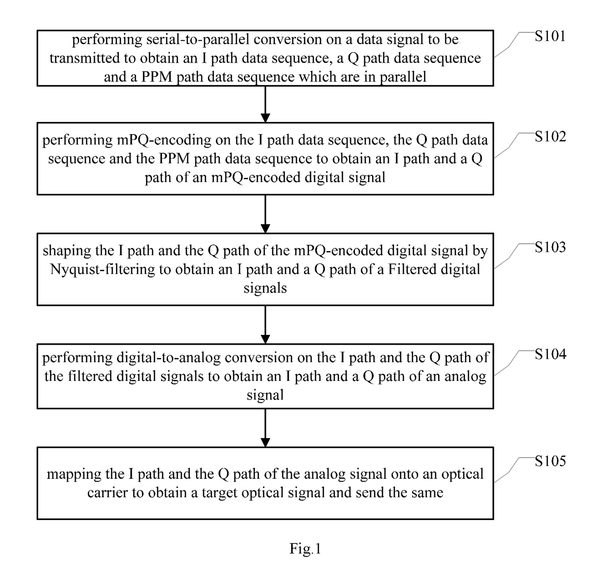
[0075]The embodiments of the present application provide a method for sending and receiving an optical signal, and the present application is specifically described below by means of detailed embodiments.

[0076]It should be explained in advance that in the combined encoding of M-ary Pulse Position Modulation (mPPM) and Quadrature Phase-Shift Keying (QPSK) (mPQ-encoding) method according to the embodiments of the present application, the M-ary Pulse Posit...


PUM


Abstract

The embodiments of the present application disclose a method and device for sending and receiving an optical signal. The method for sending an optical signal comprises: performing serial-to-parallel conversion on a data signal to be transmitted to obtain an I path data sequence, a Q path data sequence and a PPM path data sequence which are in parallel; performing mPQ-encoding on the I path data sequence, the Q path data sequence and the PPM path data sequence to obtain an I path and a Q path of an mPQ-encoded digital signal; shaping the I path and the Q path of the mPQ-encoded digital signal by Nyquist-filtering to obtain an I path and Q path of a filtered digital signal; performing digital-to-analog conversion on the I path and the Q path of the filtered digital signal and mapping the converted I path and Q path onto an optical carrier to obtain a target optical signal and send the same. By applying the embodiments of the present application, spectral efficiency loss in optical communication can be reduced or even eliminated while power efficiency is increased.

Description

CROSS REFERENCE TO RELATED APPLICATION[0001]The present application claims the benefit of priority to Chinese Patent Application No. 201610144598.0, filed on Mar. 14, 2016,and entitled “Method and Device for Sending and Receiving an Optical Signal”, which is hereby incorporated into the present application by reference herein in its entirety.TECHNICAL FIELD[0002]The present application relates to the technical field of optical communication, in particular to a method and device for sending and receiving an optical signal.BACKGROUND[0003]In an optical communication system, information is transmitted by using optical signals of different modulation formats as carriers. Modulation format is mainly used for carrying and transmitting information. Requirement for modulation formats mainly aims at fast transmission rate and good signal quality, wherein the indicator for measuring the transmission rate is spectral efficiency and the indicator for measuring the transmission quality is power ...

Claims


Application Information

Patent Timeline
Patent Type & Authority Patents(United States)
IPC IPC(8): H04L1/00H04B1/00H04B10/516H04B10/556
CPCH04B10/5161H04L1/00H04B10/5561H04B1/0042
Inventor LI, YANYU, MIAOWU, JIANPANG, JIANGCHUANKONG, DEMING
Owner BEIJING UNIV OF POSTS & TELECOMM
Why Eureka
Try Eureka