Drive device for hybrid vehicle

a hybrid vehicle and drive device technology, applied in the direction of vehicle sub-unit features, transportation and packaging, gear arranging, etc., can solve the problems of difficult installation of bearings that support the driven gear b, and difficulty in ensuring the rigidity of one bearing against these loads, so as to increase the rigidity of the bearing, which is arranged on the inner peripheral side.

Active Publication Date: 2018-10-30
TOYOTA JIDOSHA KK
View PDF20 Cites 1 Cited by
  • Summary
  • Abstract
  • Description
  • Claims
  • Application Information

AI Technical Summary

Benefits of technology

[0007]The present invention provides a structure of a drive device for a hybrid vehicle that can suppress rattling sound generated on a rotor shaft and ensure supporting rigidity of each rotational shaft, the drive device for a hybrid vehicle including an engine and a motor arranged on different rotational axes.
[0017]In the above aspect, the second bearing and the third bearing may be arranged at a position where the second bearing and the third bearing at least partially overlap in a radial direction. According to the above aspect, since the second bearing and the third bearing at least partially overlap in the radial direction, supporting rigidity of the bearing, which is arranged on the inner peripheral side, is increased.

Problems solved by technology

For this reason, it is difficult that one bearing ensures the supporting rigidity against these loads.
However, as shown in FIG. 6, since the driven gear 56 is directly fitted to the rotor shaft 22a, and there is no space to install a bearing that supports the driven gear 56, it is difficult to install the bearing that supports the driven gear 56.

Method used


Image

  • Drive device for hybrid vehicle
  • Drive device for hybrid vehicle
  • Drive device for hybrid vehicle

Examples


Embodiment Construction

[0025]A detailed description will hereinafter be made on examples of the present invention with reference to the drawings. Noted that, in the following examples, the drawings are appropriately simplified or modified. Thus, a dimensional ratio, a shape, and the like of each component are not necessarily depicted precisely.

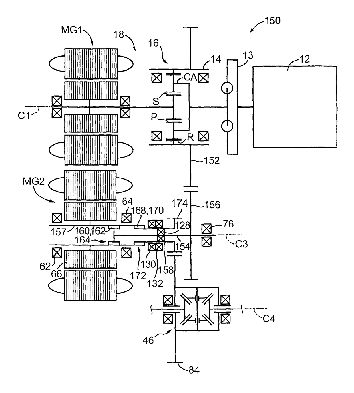
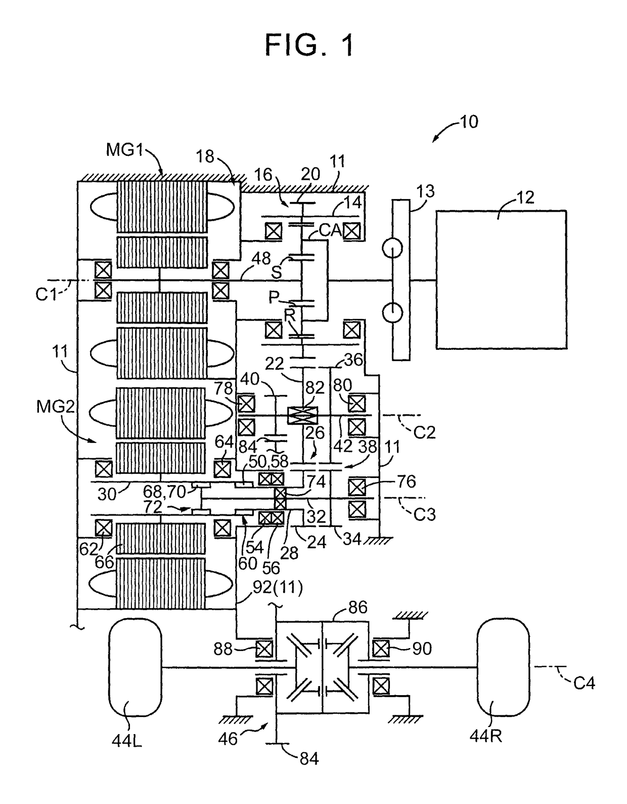
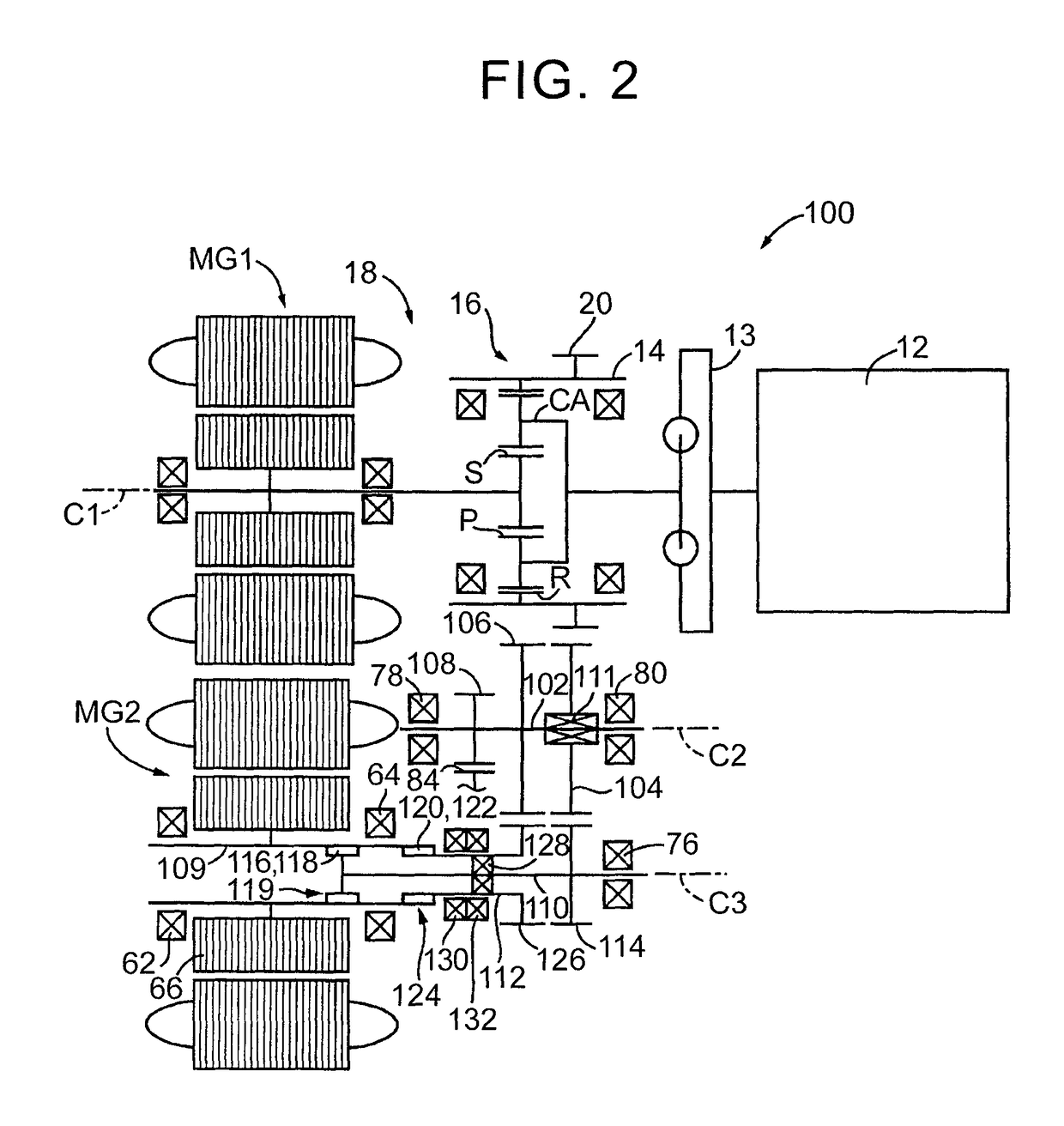
[0026]FIG. 1 is a schematic view of a configuration of a drive device 10 for a hybrid vehicle (hereinafter, a drive device 10) that is an example of the present invention. The drive device 10 is configured by including an engine 12 and a differential mechanism 16 in a case 11 as a non-rotational member. The engine 12 is a primary drive power source of a vehicle. The differential mechanism 16 splits power that is transmitted from the engine 12 via a damper device 13 to a first motor MG1 and an output member 14. The drive device 10 is configured by including: an electrical differential section 18, a second motor MG2, a speed increasing mechanism 26, a driven gear shaf...


PUM


Abstract

An engine and a motor are arranged on different rotational axes. A driven gear shaft is arranged to rotate about the rotational axis shared with a rotor shaft of the motor. The driven gear shaft is connected to the rotor shaft of the motor for power transmission. The rotor shaft is rotatably supported by a first bearing. The rotor shaft and the driven gear shaft are formed of different shafts. The driven gear shaft is configured to extend in a shaft direction toward the rotor shaft side. A second bearing is arranged in an extended portion. The output shaft is arranged to rotate about the rotational axis shared with the rotor shaft of the motor. The output shaft is connected to the rotor shaft for power transmission. The output shaft is connected to a drive wheel for power transmission.

Description

BACKGROUND OF THE INVENTION[0001]1. Field of the Invention[0002]The present invention relates to a drive device for a hybrid vehicle, and in particular to a structure of a drive device in which an engine and a motor are arranged on different rotational axes.[0003]2. Description of Related Art[0004]For a drive device for a hybrid vehicle that includes an engine and a motor, a structure has been suggested in which the engine and the motor are arranged on different rotational axes. For example, a drive device for a hybrid vehicle that is described in Japanese Patent Application Publication No. 2012-017007 (JP 2012-017007 A) or, Japanese Patent Application Publication No. 2006-341849 (JP 2006-341849 A) is such an example. Since the engine and the motor are arranged in the different rotational axes as described above, an axial length of the drive device can be reduced in comparison with a case where the engine and the motor are arranged on a common rotational axis. In the drive device fo...

Claims


Application Information

Patent Timeline
Patent Type & Authority Patents(United States)
IPC IPC(8): B60K6/48B60K6/40B60K6/36F16H3/08B60K6/445F16H3/72F16H57/021F16H37/08F16H57/02
CPCB60K6/36B60K6/40B60K6/445F16H3/728F16H57/021B60Y2200/92Y10S903/909F16H2037/0873F16H2057/02034F16H2057/02043F16H2200/2005F16H2200/2064Y02T10/6239B60Y2400/70Y02T10/62
Inventor SUGIYAMA, MASATAKAIBARAKI, RYUJIKIMURA, HIROAKIKUWAMOTO, HIROKI
Owner TOYOTA JIDOSHA KK
Why Eureka
Try Eureka