Brushless motor

一种无刷电动机、电动机的技术,应用在电动组件、电气元件、机电装置等方向,能够解决难以确保连结强度、无法实行等问题,达到部件便宜、防止飞溅、改善便易性的效果

Inactive Publication Date: 2010-11-17
MINEBEA MOTOR MFG
View PDF3 Cites 0 Cited by
  • Summary
  • Abstract
  • Description
  • Claims
  • Application Information

AI Technical Summary

Problems solved by technology

[0014] Should Figure 14 The bearing retention mechanism shown is also compatible with Figure 13 In the example shown, the fixing by welding is difficult due to the limitation of its structure, and the fixing by bonding is impossible because of the fear that the adhesive will flow to the bottom of the motor mounting plate.
[0015] In short, it can be clearly understood that with the miniaturization and thinning of motors, it is difficult to ensure the connection strength only by press-fitting.

Method used


Image

  • Brushless motor
  • Brushless motor
  • Brushless motor

Examples


Embodiment 1

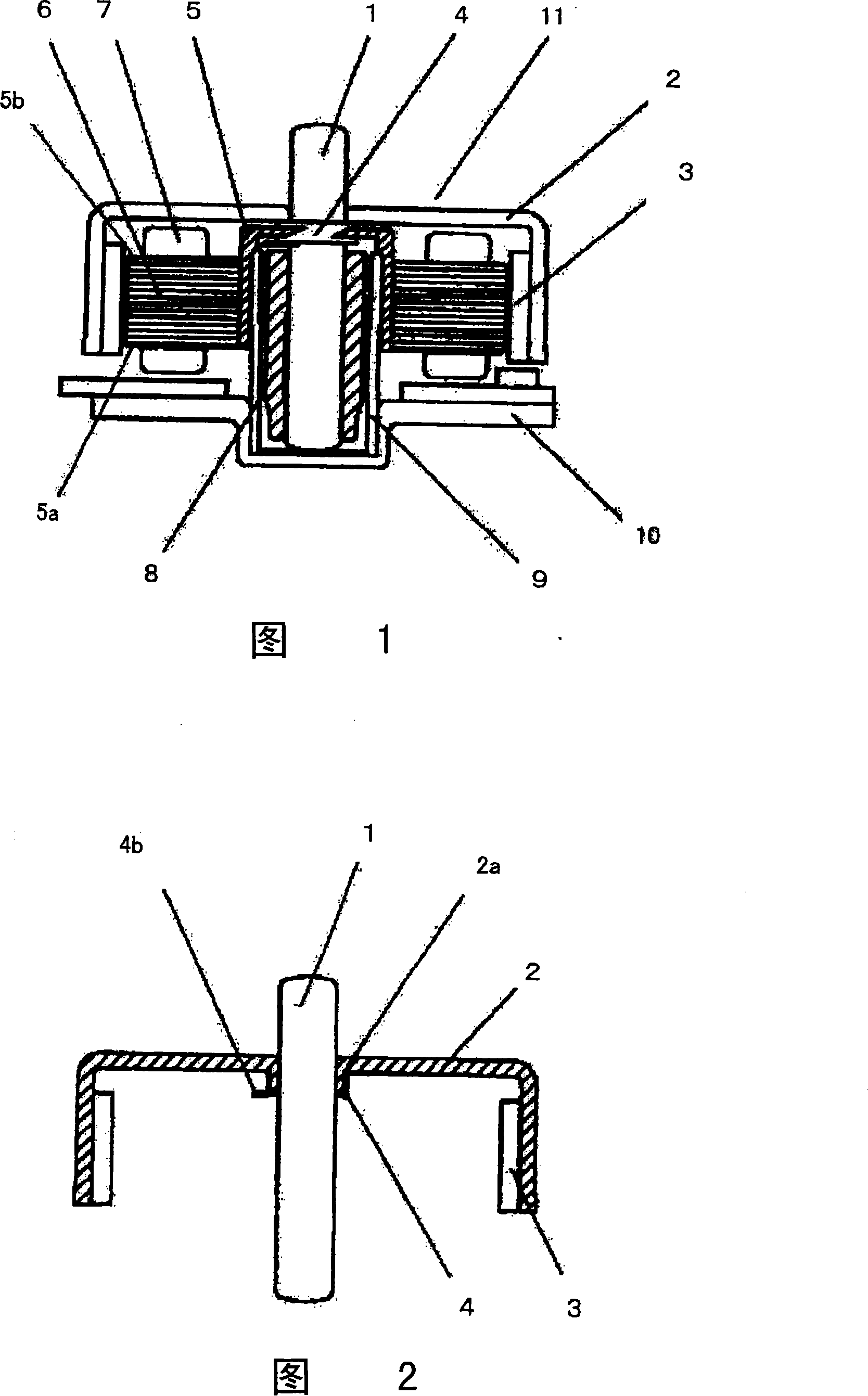
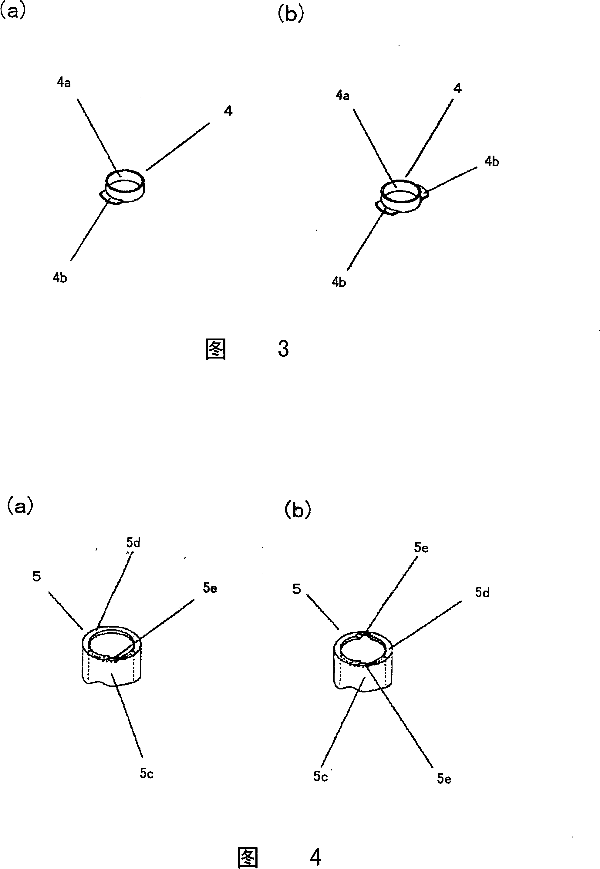
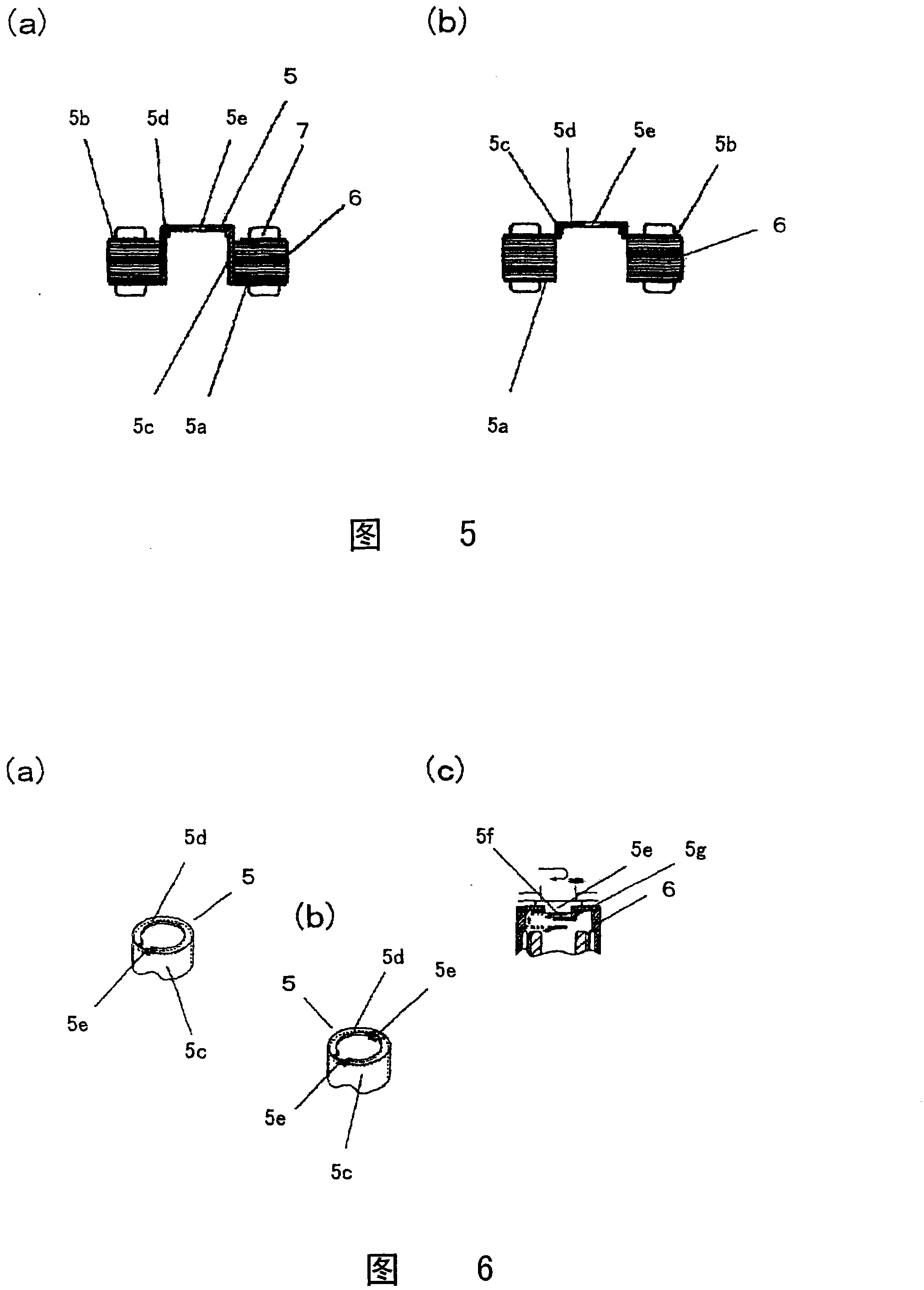
[0041] Such as figure 1 As shown, the brushless motor 11 is composed of the following rotor assembly and stator assembly. The rotor assembly consists of a rotor frame 2 with a shaft 1 fixed in the center, a rotor magnet 3 mounted on the inner peripheral side of the rotor frame 2, The engaging member 4 mounted on the fixed portion of the shaft 1 on the top surface of the rotor frame 2 is constituted; the stator assembly is composed of a bearing 8 that rotatably supports the shaft 1, and holds the bearing 8 on its inner periphery. The cylindrical bearing housing 9 on the side, the motor mounting plate 10 that fixes and holds the bearing housing 9 in the center by press-fitting, etc., the stator core 6 installed on the outer peripheral side of the bearing housing 9, and the gasket is assembled on the The insulating members 5 a and 5 b on the surface of the stator core 6 are formed by a coil 7 wound with wires and a fall-off preventing member 5 mounted on the stator core 6 .

[...

Embodiment 2

[0048] Figure 9 and Figure 10 (a), Figure 10 (b) shows the brushless motor of (Example 2) of this invention.

[0049] Such as Figure 9 As shown, the brushless motor is composed of a rotor portion 33 and a stator portion 40 .

[0050] The rotor part 33 has: a turntable part 28 for placing the disc, a rotor frame case 29, a disc alignment member 30 supporting the disc together with the turntable part 28, a rotor magnet 31 mounted on the rotor frame case 29, And the shaft 1 fixed to the center of the above-mentioned rotor frame case 29 .

[0051] The stator part 40 has: a bearing 8 supporting the above-mentioned shaft 1, a bearing housing 9 holding the bearing 8, an axial thrust stopper 36 supporting the shaft 1 in the axial direction, and a coil wound with a rotor magnet 31 opposite to the above-mentioned rotor magnet 31. 37 iron core 38, and the motor mounting plate 10 holding the above-mentioned bearing housing 9.

[0052] The bearing housing 9 is integrally formed i...

Embodiment 3

[0056] Figure 11 (a), Figure 11 (b) shows Example 3 of the present invention.

[0057] Figure 9 In this example, the bottom of the recess 10a of the motor mounting plate 10 is flat, and the base end of the bearing housing 9 fits in the recess 10a only with its outer circumference. A groove 41 into which the base end of the bearing housing 9 fits is formed at the bottom of the bearing housing 9 . Other components of brushless motors and Figure 9 same.

[0058] In detail, such as Figure 11 As shown in (a), a groove 41 is also integrally provided on the bottom surface of the recess 10 a formed in the motor mounting plate 10 . The axial thrust baffle 36 is provided on the inner side than the groove 41 .

[0059] Additionally, if Figure 11 As shown in (b), the above-mentioned groove 41 is further formed with protrusions 42 at several positions whose height is set to be lower than the inner diameter side wall surface 43 of the fitting groove. This is a projection at t...


PUM


Abstract

An brushless motor, which use bearing and bearing shell rotatable support the axes of roter on the dish driving mchanism of motor panel of the stator, the character is that, the bearing shell mold as barrel-type which in the internal circumstance of the bearing, and support the butt end on the said motor panel; freely revolve support the end panel of axile of the said bearing, immediacy touch themotor panel or separate by the axial thrust baffle, so as to get axis supporting.

Description

[0001] The patent application for the present invention is a divisional application of the patent application for invention with the application number 200510084461.2, the application date being July 8, 2005, and the name "brushless motor". technical field [0002] The present invention relates to a brushless motor for rotating discs such as CD (Compact Disc), DVD (Digital Versatile Disc), and MD (MiniDisc). Background technique [0003] Conventionally, in order to prevent the rotor from falling off when a force exceeding the magnetic attraction force between the rotor magnet and the stator core acts on the motor due to impact or the like, brushless motors have been provided with a structure to prevent falling off. As the structure for preventing falling off, generally adopt a structure in which an engaging portion is provided on the bearing housing, a falling-off preventing member is provided on the rotor portion facing the bearing housing, and the two are engaged (refer to,...

Claims


Application Information

Patent Timeline
Patent Type & Authority Patents(China)
IPC IPC(8): H02K5/16G11B19/20
Inventor 西方俊之久山浩二冲永钦二郎益田久光男池野弘志加纳刚
Owner MINEBEA MOTOR MFG
Why Eureka
Try Eureka