Low-floor vehicle
A low-pedal, pedal-type technology, applied in electric scooters, motorcycles, motor vehicles, etc., can solve the problems of difficult adjustment, increased weight and cost, and achieve reduced deflection, effective torsional characteristics, and improved rotation. Effect
- Summary
- Abstract
- Description
- Claims
- Application Information
AI Technical Summary
Problems solved by technology
Method used
Image
Examples
Embodiment 1
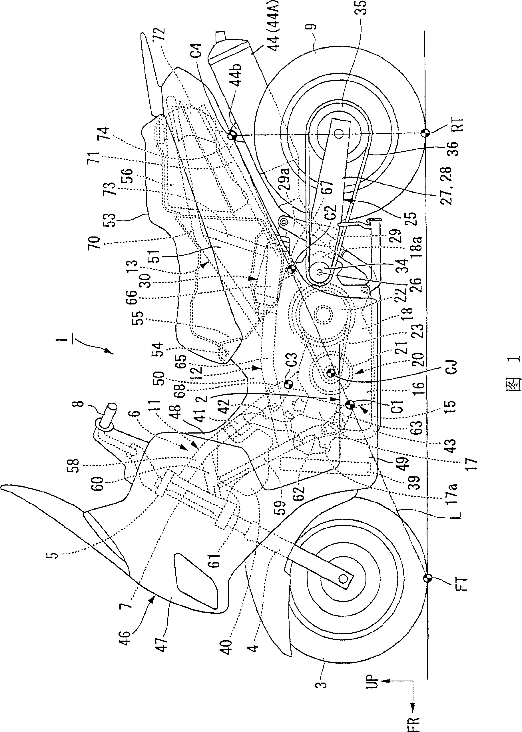
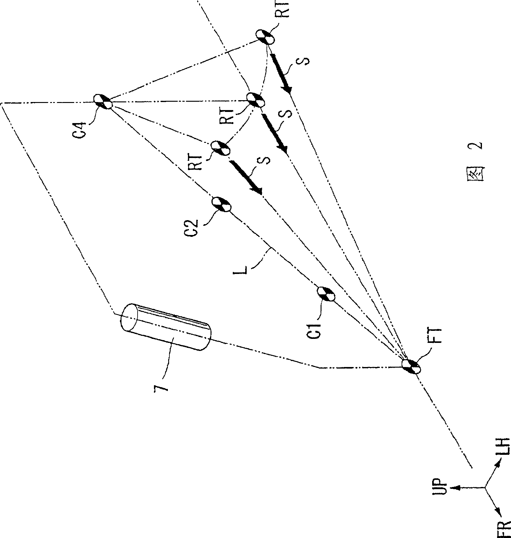
[0052] The two-wheeled motor vehicle 1 shown in Fig. 1 is a small motorcycle (low-pedal type vehicle) having a foot resting portion for the occupant, that is, a low-pedal portion 2, and its front wheels 3 are pivotally supported on left and right front forks 4, each front The fork 4 is operably pivotally supported on a head pipe 7 at the upper front end of the vehicle frame 6 via a handle bar 5 , and a handle 8 for steering is attached to the upper part of the handle bar 5 . Here, the contact portion of the front wheel 3 (front wheel contact portion) is denoted by symbol FT in the figure.
[0053] The frame 6 is integrally combined with various steel materials by welding etc., and mainly consists of the lower frame 11 extending obliquely rearward and downward from the head pipe 7 , and the main frame above the engine 15 extending rearward from the lower part of the lower frame 11 and passing through the inner side of the low pedal part 2 12 and a seat frame 13 extending obliqu...
no. 2 example
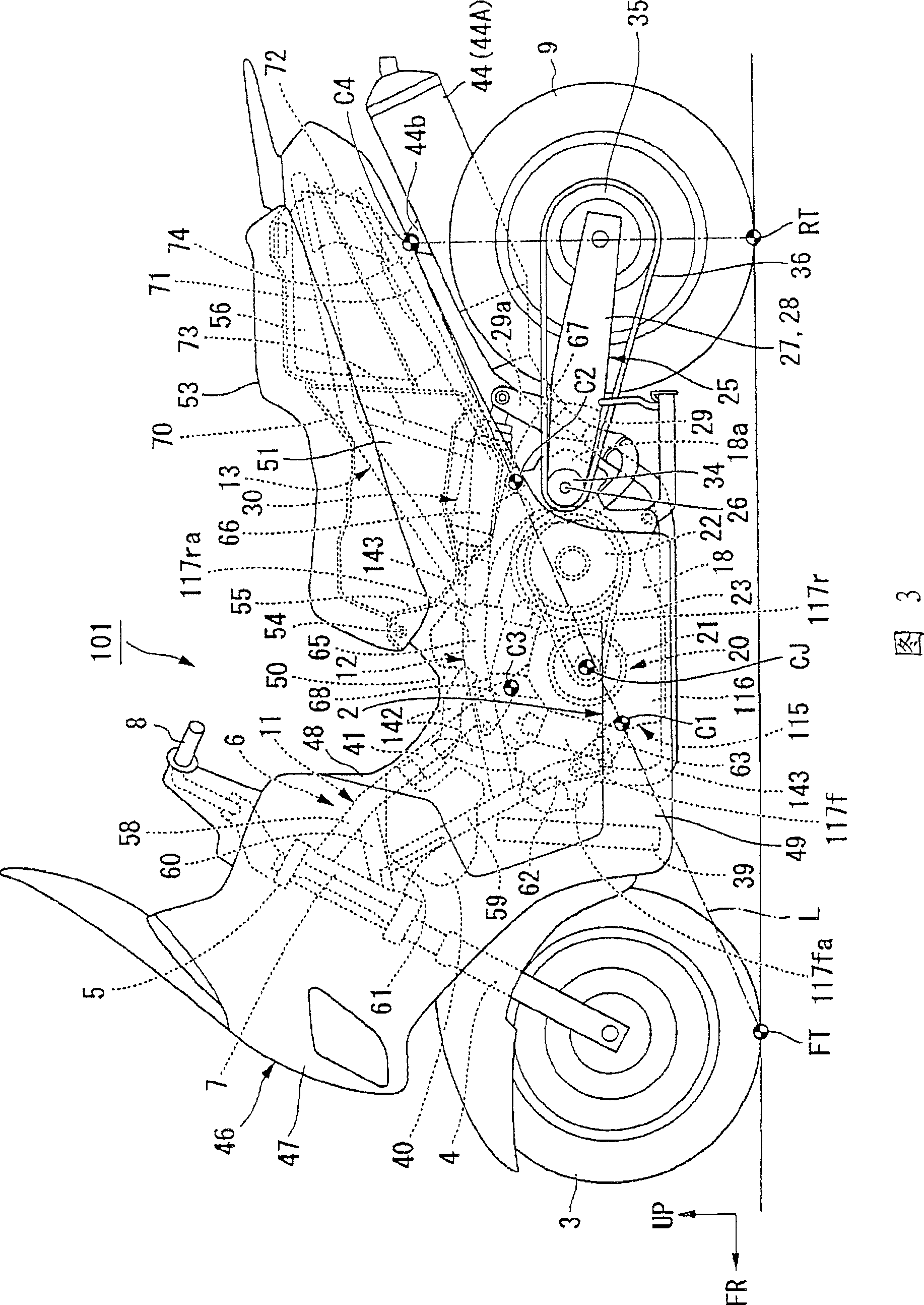
[0087] In this second embodiment, only the form of the engine is different from the above-mentioned first embodiment, and other parts that are the same as those in the first embodiment are denoted by the same symbols and descriptions thereof are omitted.
[0088] As shown in FIG. 3 , the engine 15 which is the prime mover of the motorcycle 101 is, for example, a water-cooled four-stroke V-type twin-cylinder engine. The cylinder 117f and the rear engine 117r are erected substantially upward from the upper portion of the crankcase 116 . The transmission case 18 is connected to the rear of the crankcase 116 .
[0089] The radiator 39 is arranged in front of the front cylinder head 117fa, the air cleaner 40 is arranged above the radiator 39, and the intake pipes 142 branched and extended from the throttle body 41 connected to the rear of the air cleaner 40 are respectively It is connected to the intake ports on the upper part of the front cylinder head 117fa and the front part of...
PUM
 Abstract
Description
Claims
Application Information
 - R&D
- Intellectual Property
- Life Sciences
- Materials
- Tech Scout
- Unparalleled Data Quality
- Higher Quality Content
- 60% Fewer Hallucinations
Browse by: Latest US Patents, China's latest patents, Technical Efficacy Thesaurus, Application Domain, Technology Topic, Popular Technical Reports.
© 2025 PatSnap. All rights reserved.Legal|Privacy policy|Modern Slavery Act Transparency Statement|Sitemap|About US| Contact US: help@patsnap.com


