System, method and device for a medical surgery tray

a surgical tray and system technology, applied in the field of surgical instruments, can solve the problems of unsuitable versatility for use, system limitations, and inconvenient use of general instruments, etc., to reduce surgeon and medical malpractice liability costs, efficient organise instruments, and improve safety and efficiency of relaying instruments

Active Publication Date: 2018-11-06
CERDA JOHN PAUL +2
View PDF23 Cites 0 Cited by
  • Summary
  • Abstract
  • Description
  • Claims
  • Application Information

AI Technical Summary

Benefits of technology

[0013]The trays use unique features and elements that standardize and efficiently organize instruments. The method improves the safety and efficiency of relaying the instruments during the surgical procedure. The surgical tray of the present invention can be conventionally sterilized and purposefully arranges surgical instruments in a perpendicular fashion in a space and manor similar to that used by surgical scrub nurses on their conventional Mayo stand and back tables, as well as to hold, and display with easy access, a predetermined number of surgical instruments in pre-designated locations. This serves to safe guard against commonly occurring sharps injuries to the patient and staff members of the preoperative setup, intraoperative procedure, and the post-operative re-sterilization process, in addition to preventing post-operative retained foreign objects in patients, effectively decreasing surgeon and medical malpractice liability costs. Additionally, the trays and back table drape, used in the method of set up contemplated, facilitates faster, more efficient and accurate accounting of surgical instruments and materials present in the operating room.
[0051](Z) The disclosed trays, in one embodiment, are constructed using a modular component design comprising a base containment platform which is designed to rest on a Mayo stand. The interior section of each tray is divided up into four separate component sections which are attached, fashioned and joined to the base unit using attachment locking mechanisms to fasten and hold all of the components in place. This allows the end-user to exchange and replace sections of trays as needed without replacing the entire tray system. The functional design characteristics, intended use and applications remain the same, providing the same benefits as all other embodiments of the design and system.

Problems solved by technology

However, such systems have limitations.
For example, one type of tray, although well adapted for use in a first surgical procedure, is ill suited for a second type of surgical procedure.
A general instrument tray, commonly used in many operating room procedures, is not suitably versatile to adapt for use as operating room procedures change, are modified, or are replaced with new procedures.
The lack of standardization causes delays in both the initial preparation of the instruments and, more critically, during surgery, especially when a scrub nurse is commonly relieved during a procedure.
This is a known limitation of the aforementioned method.
While many of these known trays include additional mechanisms or features configured to hold specific individual instruments in a preferred orientation, they are not optimized to hold a large quantity of varying instruments in an “operation ready” position.
However, this is disadvantageous as the removable dividers must be accounted for and can be dislodged during use.
This adds risk by potentially becoming lost inside the patient during surgery, or simply dislodged causing one or more instruments to be disrupted while on the tray, thus delaying the surgical process, for example.
One known device in the art is a multipurpose surgical instrument tray disclosed by Smith in U.S. Pat. No. 6,426,041, and issued on 2002 Jul. 2. One significant limitation of the Smith device, as illustrated best in FIG. 3 of Smith, is that both a portion of the ring-end of a surgical instrument and the “sharp” end of the same instrument rests above, or stands proud, in relation to a first flat top surface of the tray.
This enables users to be cut or punctured by the sharp end of the instrument, which is very undesirable.
It also leaves the sensitive tips of the medical instruments exposed and subject to damage and degradation, thus requiring replacement often.
However, the success is limited as frequently these sharps protective tips must be carefully examined prior to use and the sharp instrument frequently cuts through the protective tip and wrapper or package.
This methodology is limited in that it relies upon visual inspection by a trained, naked eye, and as such is highly variable and prone to human error.
Thus presents a major disadvantage, as it is known that these discarded protective tips may manage to find a way into the patient; this presents as a foreign object with ensuing poor patient outcomes and resultant adverse legal implications.
To date there is no known or proven methodology that adequately protects the patient and the users from sharps injury, while at the same time securing and protecting the surgical instruments themselves from damage and facilitating a faster more accurate accounting of instruments and materials at all relevant times of a surgical operation.

Method used


Image

  • System, method and device for a medical surgery tray
  • System, method and device for a medical surgery tray
  • System, method and device for a medical surgery tray

Examples


Embodiment Construction

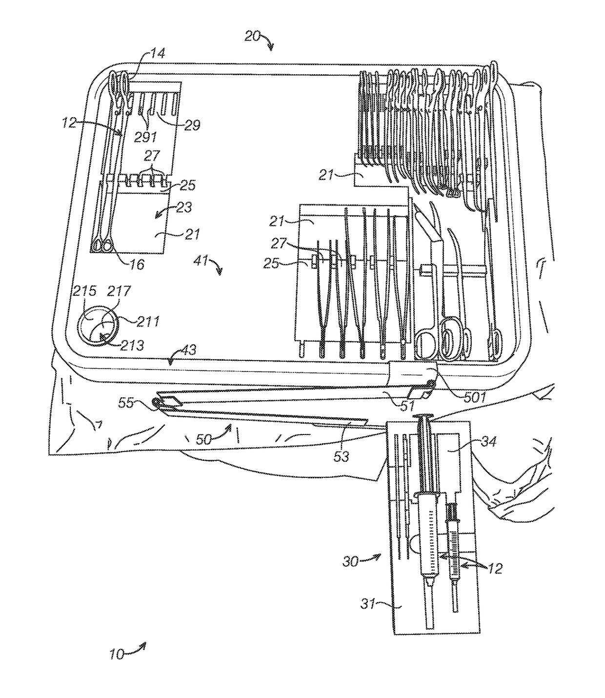
[0068]The disclosed trays, systems and methods will become better understood through review of the following detailed description in conjunction with the figures. The detailed description and figures provide merely examples of the various inventions described herein. Those skilled in the art will understand that the disclosed examples may be varied, modified, and altered without departing from the scope of the inventions described herein. Many variations are contemplated for different applications and design considerations; however, for the sake of brevity, each and every contemplated variation is not individually described in the following detailed description.

[0069]Throughout the following detailed description, examples of various trays, systems and methods are provided. Related features in the examples may be identical, similar, or dissimilar in different examples. For the sake of brevity, related features will not be redundantly explained in each example. Instead, the use of rel...


PUM


Abstract

A method and system for organizing surgical instruments and supplies in an operating room in preparation for surgery using a system having two tray devices. Each tray includes at least one flat work surface disposed in a first reference plane; an edge feature surrounding the at least one flat work surface, the edge surface standing proud at a predetermined first positive offset distance from the first reference plane, the edge feature comprising at least a work-surface-side wall intersecting the at least one flat work surface at substantially about 90-degrees at a top surface coupled to the work-surface-side wall, wherein the top surface disposes generally parallel to the first reference plane and is further defining the first positive offset distance measured from the reference plane; and at least one recessed compartment comprising a bottom surface disposed parallel to the first reference plane and offset therefrom at a first negative offset distance.

Description

PRIORITY CLAIM[0001]The present application claims benefit under 35 USC Section 119(e) of U.S. Provisional Patent Application Ser. No. 62 / 263,022 filed on 4 Dec. 2015 titled “System, Method, and Device for a Medical Surgery Tray” by a common inventor: The present application is based on and claims priority from this application, the disclosure of which is hereby expressly incorporated herein by reference.FIELD OF THE INVENTION[0002]This invention relates generally to surgical instruments and, more specifically, to a standardized procedural methodology utilizing trays for transporting sterile surgical instruments to an operating room and presenting the instruments in a standardized configuration and order, ready-to-use and appropriate for nearly all types of surgery.BACKGROUND[0003]Storage and sterilization systems for veterinary and human dental and medical instruments are known in the art. Many devices include features to stack and space. In the art of medical surgical instruments,...

Claims


Application Information

Patent Timeline
Patent Type & Authority Patents(United States)
IPC IPC(8): B65D83/10A61B46/00A61B50/33B65B55/04A61B46/10B65B55/12A61B50/30A61B90/94
CPCA61B50/33A61B46/00A61B46/10B65B55/12B65B55/04A61B2050/3009A61B90/94A61B2050/3008
Inventor CERDA, JOHN PAULLOWENSTEIN, MARKCERDA-GUTIERREZ, JULIO ARMANDO
Owner CERDA JOHN PAUL
Why Eureka
Try Eureka