Temperature measuring device for a respiratory humidifier

a technology of temperature measurement and humidifier, which is applied in the direction of optical radiation measurement, instruments, other medical devices, etc., can solve the problems of reducing the flow rate, complicated and expensive, and difficult to manufacture a flow channel with a hollow body, so as to increase the turbulence of the breathing gas stream, increase the uptake of moisture and heat, and heat up more quickly

Active Publication Date: 2018-11-06
HAMILTON MEDICAL AG
View PDF8 Cites 0 Cited by
  • Summary
  • Abstract
  • Description
  • Claims
  • Application Information

AI Technical Summary

Benefits of technology

[0008]According to one aspect of the invention, a temperature-measuring device is provided for a respiratory humidifier comprising a liquid container, wherein the temperature-measuring device comprises a flow channel for breathing gas and an infrared detector, which is directed from the outside toward the flow channel for the contactless detection of the temperature of the breathing gas in the flow channel, wherein the flow channel comprises, on its lateral surface, a measurement portion, which is aligned with the surrounding lateral surface areas and at which the infrared detector is directed, wherein the flow channel comprises a flow guide element, which conducts the breathing gas stream at a previously determined inflow angle of preferably greater than 10° and less than 170° to the measurement portion. The arrangement of the measurement portion on the lateral surface of the flow channel represents a simple design, because the measurement portion does not project from the lateral surface as it does in the case of DE 10 2007 037 955 A1, for example. The “lateral surface” as understood here is, for example, the wall surface of a cylindrical flow channel or a flat wall of a channel with a rectangular or polygonal cross section. Such flow channels can be designed as integral parts of the liquid container and can be easily produced at low cost either individually or together with the liquid container. The measurement portion is aligned two-dimensionally and more-or-less continuously with the surrounding areas of the lateral surface and / or is flush with those surfaces.
[0009]The inflow angle is preferably in the range from about 30° to about 60° and even more preferably in the range from about 40° to about 50°. A breathing gas stream striking the flow guide element set at this inflow angle is deflected directly onto the measurement portion, and as a result of its impact on the measurement portion, the breathing gas stream transfers a portion of its heat especially effectively to the material of the measurement portion. The temperature of the measurement portion thus corresponds even more accurately to what is essentially the temperature of the incident breathing gas stream.
[0010]It is especially advantageous for the flow guide element to be arranged in the interior of the flow channel. The flow guide element can be preferably a straight or a curved plate. With a flow guide element of this design, a breathing gas stream arriving in the longitudinal direction of the flow channel, for example, can be deflected at the preferred inflow angle. A flow guide element of this type in the interior of the flow channel is relatively easy to manufacture.
[0013]It is also advantageous for the surface of the flow guide element to have a structure. One possible structure is, for example, a set of holes; alternatively, the plate might be roughened or comprise a plurality of elevations or depressions, which can be of different shape, and so on. The structured surface serves to increase the turbulence of the breathing gas stream, so that it brings about the most homogeneous possible heating of the measurement portion. In addition, the turbulence of the breathing gas stream can also be helpful in increasing the uptake of moisture and heat by the breathing gas stream.

Problems solved by technology

The disadvantage of this design of a temperature-measuring device is that it is not easy to manufacture a flow channel with a hollow body projecting into it, because either the hollow body must be formed out of the same material as the flow channel or perhaps bonded to it in a second production step, or alternatively the flow channel and the hollow body must be produced by means of separate molds, which is complicated and expensive.
In addition, the hollow body in the flow channel is responsible for a relatively high flow resistance, which interferes with the flow of the breathing gas stream and thus reduces the flow rate.

Method used


Image

  • Temperature measuring device for a respiratory humidifier
  • Temperature measuring device for a respiratory humidifier
  • Temperature measuring device for a respiratory humidifier

Examples


Embodiment Construction

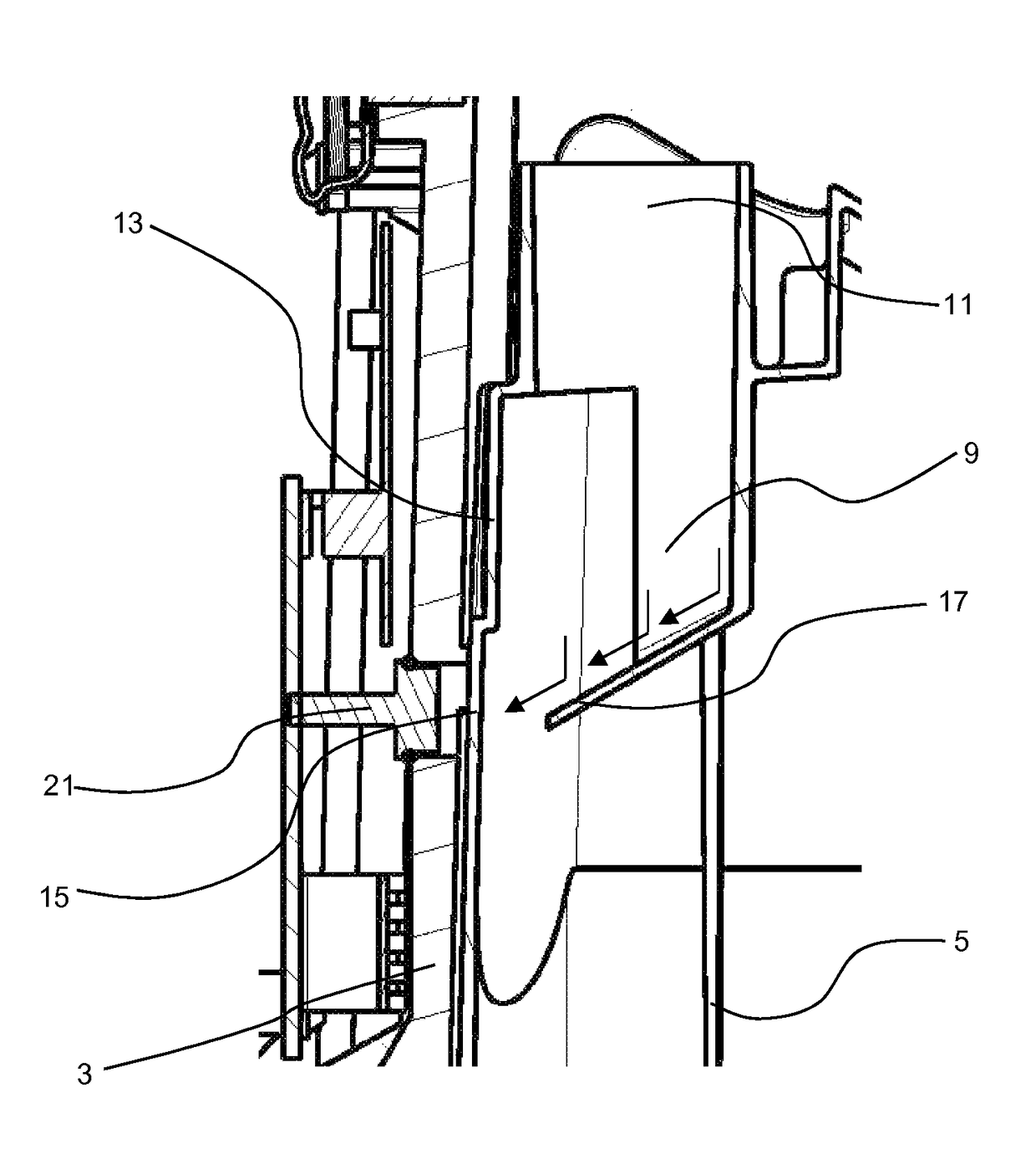
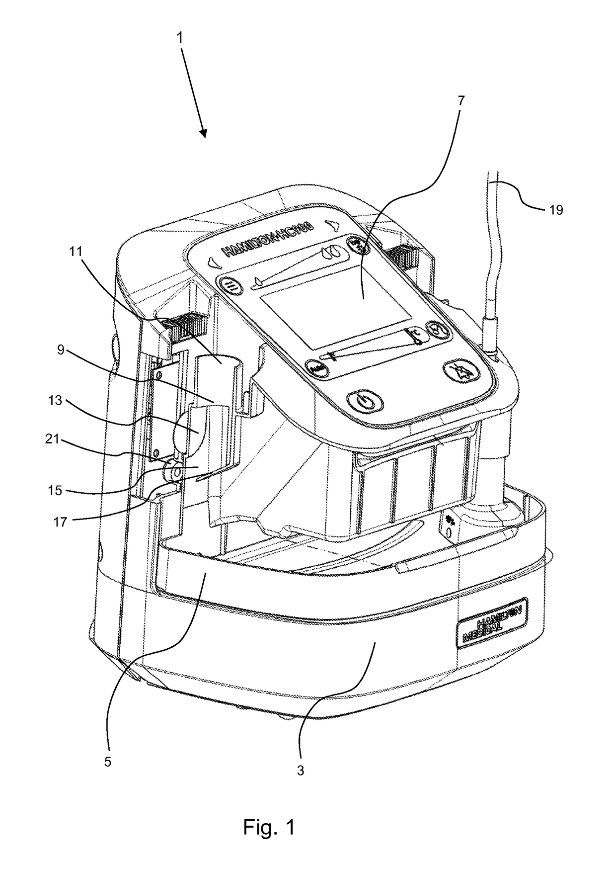
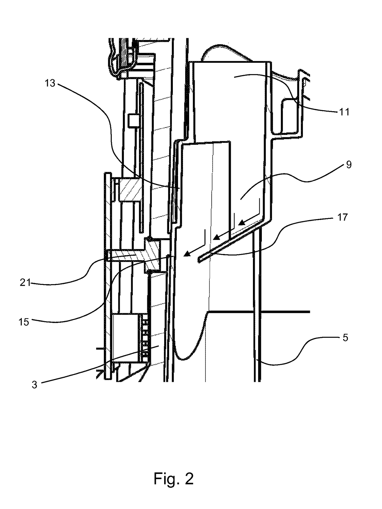
[0023]FIG. 1 shows a perspective view of a respiratory humidifier 1 with a housing 3 and a liquid container 5, inserted detachably into the housing 3, wherein parts of the housing 3 and of the liquid container 5 have been cut away to facilitate a better understanding of the invention. The liquid container 5 has an essentially U-shaped cross section in the horizontal direction, so that, after it has been inserted laterally / horizontally into the housing 3, it surrounds the central projecting section of the housing 3, on the top surface of which the user interface 7 with display and operating elements is arranged. In the area of the liquid container 5 shown on the left in FIG. 1, the container comprises a flow channel 9, which begins at a tubular socket 11 with a circular cross section and extends downward therefrom in the form of a lateral surface 13. The lateral surface 13, which is defined as the two-dimensional wall surface surrounding the flow channel 9, comprises a measurement po...


PUM


Abstract

A temperature-measuring device for a respiratory humidifier (1) with a liquid container (5) is provided, wherein the temperature-measuring device comprises a flow channel (9) for breathing gas and an infrared detector (21), which is directed from the outside toward the flow channel (9) for the contactless detection of the temperature of the breathing gas in the flow channel (9), wherein the flow channel (9) comprises on its lateral surface (13) a measurement portion (15), which is aligned with the surrounding areas of the lateral surface (13) and toward which the infrared detector (21) is directed, wherein the flow channel (9) comprises a flow guide element (17), which conducts the breathing gas stream to the measurement portion (15) at a previously determined inflow angle of preferably greater than 10° and less than 170°.

Description

FIELD OF INVENTION[0001]The present invention pertains to a temperature-measuring device for a respiratory humidifier for ventilating patients with breathing gas.BACKGROUND OF THE INVENTION[0002]When patients are being mechanically ventilated on an intensive-care ward, for example, the patient to be ventilated is connected pneumatically to the respirator by a system of ventilation tubing. Because the breathing gas supplied to the patient must be adjusted with respect to temperature and humidity to meet the physiological needs of the patient, a respiratory humidifier is arranged in the inhalation or inspiration tube to heat and humidify the breathing gas. The respiratory humidifier usually comprises a liquid container filled with distilled water, the bottom plate of the container being in thermal contact with a heating plate in the housing, as a result of which the liquid is warmed. The inhalation gas is conducted into the liquid container, is thus humidified, and then leaves the liq...

Claims


Application Information

Patent Timeline
Patent Type & Authority Patents(United States)
IPC IPC(8): A61M16/16G01J5/08A61M16/10G01J5/02G01J5/00
CPCA61M16/16A61M16/109G01J5/0014G01J5/025G01J5/0893G01J5/0806A61M2205/3368A61M2205/3306A61M2205/3313
Inventor BUECHI, RUDOLF
Owner HAMILTON MEDICAL AG
Why Eureka
Try Eureka