Supercharge Your Innovation With Domain-Expert AI Agents!

Lighting device

a technology of light source and light bulb, which is applied in the direction of semiconductor devices for light sources, light and heating apparatus, fixed installations, etc., can solve the problems of excessive lighting, short life and frequent replacement of light bulbs or fluorescent lamps

Inactive Publication Date: 2018-11-06
LG ELECTRONICS INC
View PDF16 Cites 0 Cited by
  • Summary
  • Abstract
  • Description
  • Claims
  • Application Information

AI Technical Summary

Benefits of technology

[0012]Therefore, the present invention has been made in view of the above problems, and it is an object of the present invention to provide a lighting device in which a power unit spaced apart from a housing is easily electrically connected to a light source module and sealing therebetween is easily performed.
[0013]In addition, it is another object of the present invention to provide a lighting device having improved heat dissipation performance.

Problems solved by technology

However, these light bulbs or fluorescent lamps have a short life and thus have to be frequently replaced.
In addition, a phenomenon in which the illuminance of the conventional fluorescent lamps is gradually lowered due to degradation caused over time may excessively occur.
However, a lighting device using light emitting elements has a structure in which wiring is complicated and exposed to the outside since a power unit is located at an upper portion of a housing or at a side of the lighting device, and thus wiring work is difficult and exposed to electric danger.
In addition, when a plurality of light source modules is used in the lighting device, it is difficult to wire the light source modules.
Furthermore, when the light source modules are connected to each other, it is difficult to address waterproof problems together with the wiring.
Since the light emitting elements are easily damaged by heat in the lighting device using the same, research for efficiently dissipating heat generated by the light emitting elements is ongoing.

Method used


Image

  • Lighting device
  • Lighting device
  • Lighting device

Examples


Embodiment Construction

[0036]Reference will now be made in detail to the preferred embodiments of the present invention, examples of which are illustrated in the accompanying drawings. Wherever possible, the same reference numbers will be used throughout the drawings to refer to the same or like parts.

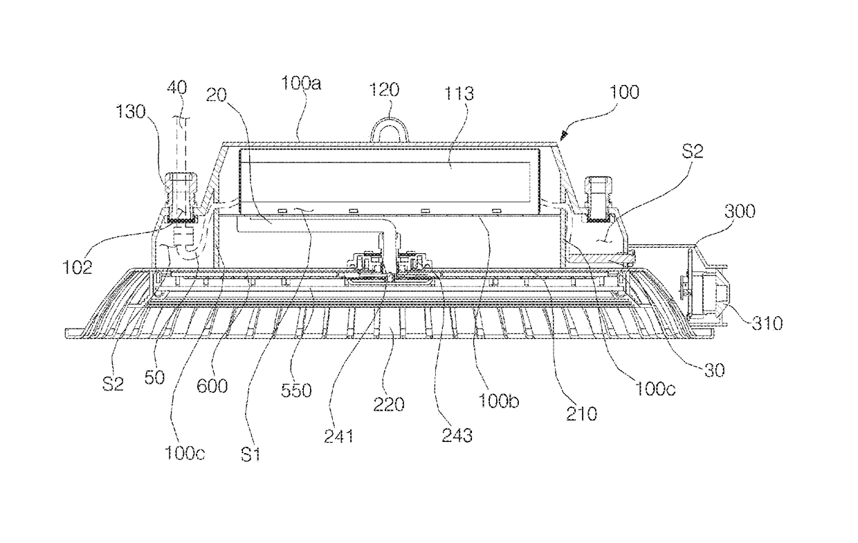
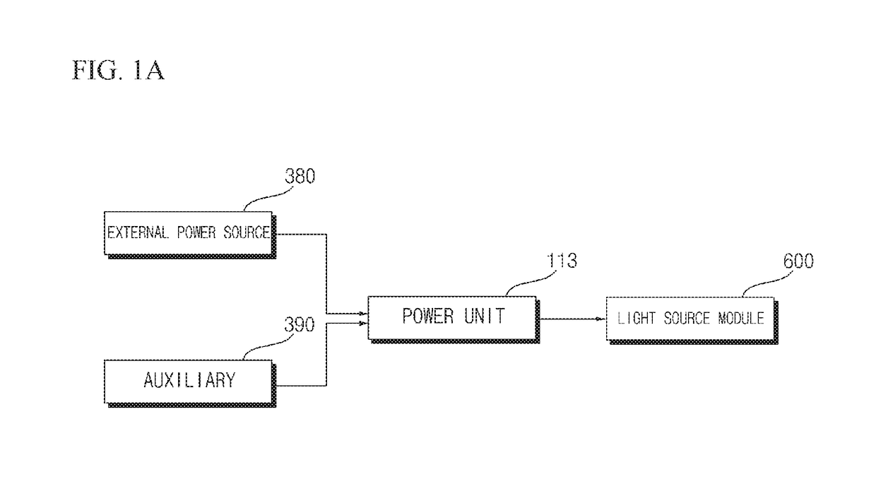
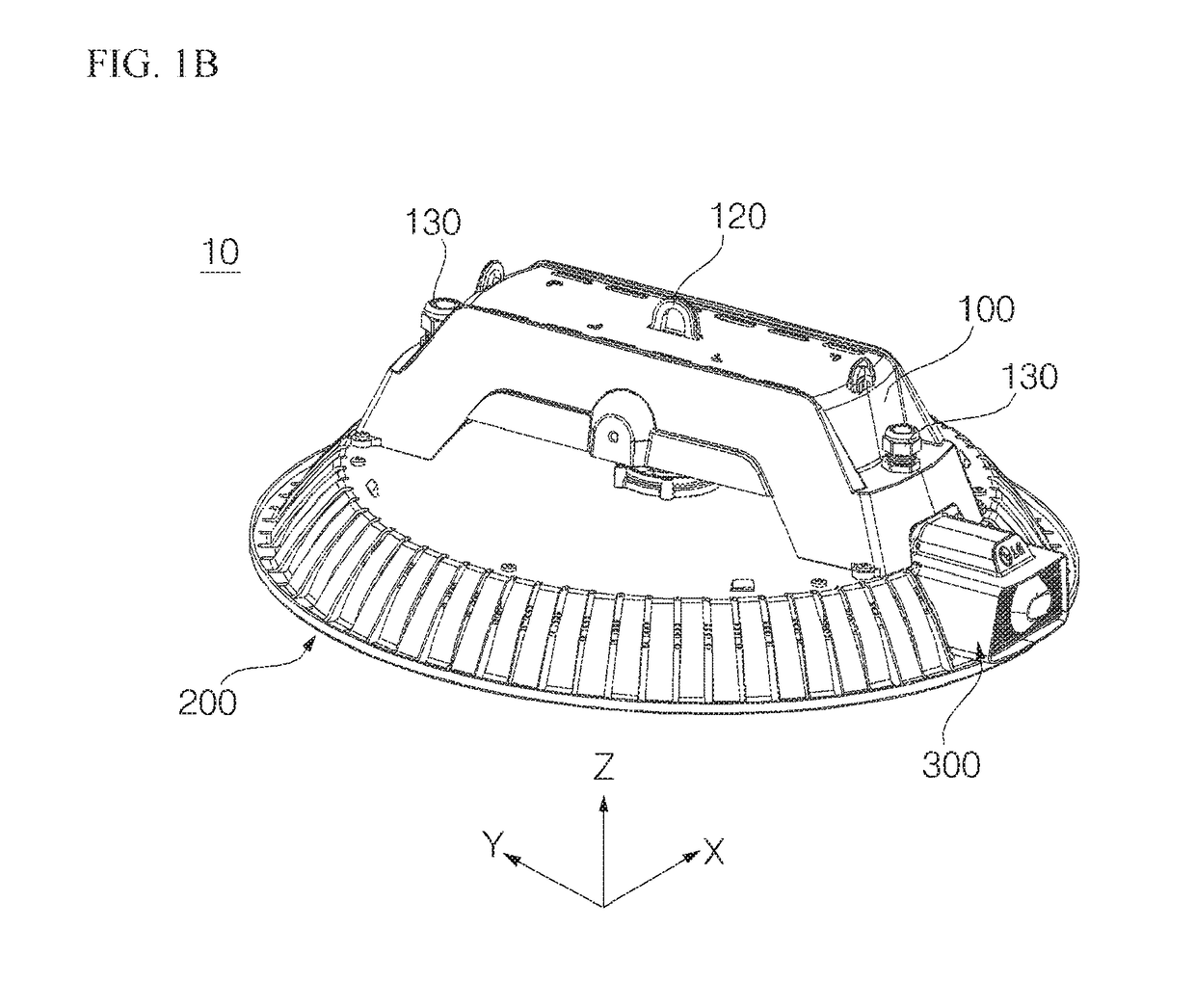
[0037]FIG. 1A is a conceptual view illustrating power connection of a lighting device according to an embodiment of the present invention. FIG. 1B is a perspective view illustrating the lighting device according to the embodiment of the present invention. FIG. 2 is a top view illustrating the lighting device according to the embodiment of the present invention. FIG. 3 is an exploded perspective view illustrating the lighting device according to the embodiment of the present invention.

[0038]A lighting device 10 according to an embodiment includes a housing 200, at least one light source module 600 (see FIG. 7) disposed on a back surface of the housing 200, a power section casing 100 which accommodates a power...


PUM


Abstract

A lighting device includes a housing, at least one light source module disposed on a back surface of the housing, and a power section casing located at an upper portion of the housing, and accommodating a power unit for controlling and supplying power to the light source module. The power section casing is divided into a power section region for accommodating the power unit and at least one junction region for providing a space in which the power unit is electrically connected to an external power source. The junction region includes therein a cable fixing section for fixing an external power source cable connected to the external power source, and a ground section electrically connected to the power unit.

Description

CROSS-REFERENCE TO RELATED APPLICATION[0001]This application claims the priority benefit of Korean Patent Application Nos. 10-2015-0016297 and 10-2015-0016298, filed on Feb. 2, 2015, in the Korean Intellectual Property Office, the entire disclosures of which are hereby incorporated by reference herein.BACKGROUND OF THE INVENTION[0002]Field of the Invention[0003]Exemplary embodiments of the present invention relate to a lighting device.[0004]Description of the Related Art[0005]In general, light bulbs or fluorescent lamps are commonly used as indoor or outdoor lighting. However, these light bulbs or fluorescent lamps have a short life and thus have to be frequently replaced. In addition, a phenomenon in which the illuminance of the conventional fluorescent lamps is gradually lowered due to degradation caused over time may excessively occur.[0006]In order to address these problems, various lighting modules employing LEDs (Light Emitting Diodes) capable of realizing improved control cha...

Claims


Application Information

Patent Timeline
Patent Type & Authority Patents(United States)
IPC IPC(8): F21V23/02F21V31/00F21S8/08F21V29/10F21V23/00F21V29/74F21V23/06F21Y105/10F21Y115/10
CPCF21V23/023F21S8/085F21V23/001F21V23/008F21V29/10F21V29/74F21V31/005F21V23/06F21Y2115/10F21Y2105/10
Inventor CHANG, HYEUKLEE, DAEHYUKCHO, MOONSUNGHAN, SANGCHULKWAK, JINSUNG
Owner LG ELECTRONICS INC
Features
  • R&D
  • Intellectual Property
  • Life Sciences
  • Materials
  • Tech Scout
  • Unparalleled Data Quality
  • Higher Quality Content
  • 60% Fewer Hallucinations
Learn More