Test pattern and method for calibrating an X-ray imaging device

a calibration method and x-ray imaging technology, applied in tomography, applications, instruments, etc., can solve the problems of affecting the accuracy of calibration and errors between ideal positions of source and/or detector with respect to objects and the positions they actually occupy, and adversely affecting the accuracy of calibration and therefore the reconstruction of 3d images. , the risk of making an error during the matching process is therefore much lower, and the calibration method is robust and reliable.

Active Publication Date: 2018-11-06
THALES SA
View PDF11 Cites 6 Cited by
  • Summary
  • Abstract
  • Description
  • Claims
  • Application Information

AI Technical Summary

Benefits of technology

[0009]The calibrating test pattern according to the invention allows robust, simple and reliable calibrating methods to be implemented. Specifically, a projection of a marker and the associated marker in the test pattern are matched from the positions of marker projections detected in an image (projection of the test pattern). However, the detection of projections of markers of the test pattern according to the invention is reliable. Specifically, it is independent of the size and shape of the markers. This detection may moreover be obtained using very simple detecting algorithms (of the circular-blob detector type). It is not necessary for these algorithms to be able to differentiate projections of markers of different geometries.
[0010]Moreover, markers and their respective projections in a 2D image or projection of the test pattern are not matched directly. They are matched by matching unique cross-ratio chains formed on the one hand by the projections of the markers and on the other hand by the markers of the test pattern. The risk of making an error during the matching process is therefore much lower than during a matching process carried out projection by projection. The test pattern according to the invention therefore makes it possible to implement robust detecting methods.
[0011]During an x-ray image capture, the geometric operation implemented is a conical projection (central projection) of the imaged body. The image of a straight line is a straight line and the cross-ratios between the distances are preserved by central projection. The risk of superposition of the images of the various markers on the border of a beam the central radius of which is substantially perpendicular to an axis perpendicular to the alignments of markers is therefore limited, thereby allowing a reliable calibration to be obtained. This property makes it possible to take into account the projections of all of the markers when performing the calibration, thereby allowing a precise calibration to be obtained. The distribution of the markers in parallel straight lines also promotes the precision and reliability of the calibration because the number of markers able to be integrated into a cylinder is high.
[0012]The distribution of the markers and therefore of the projections of the markers in straight lines allows the coded information formed by the projections of the markers, here the series of cross-ratios, to be easily extracted with a good reliability using a simple algorithm for detecting alignments in the 2D projections. It makes it possible to facilitate the matching, with a good degree of certainty, of sections of projected straight lines with the corresponding straight lines in the test pattern. Moreover, the known arrangement of the markers in straight lines and therefore the a priori arrangement of the projections of markers in straight lines may allow small errors in the positions of the projections of certain markers that are not on the expected straight line to be corrected and thus a precise calibration to be obtained.

Problems solved by technology

However, because of tolerances of the moving device, there are errors between the path actually followed by each of these elements and the ideal path that it should follow.
In other words, there are errors between the ideal positions of the source and / or detector with respect to the object and the positions that they actually occupy.
However, this type of arrangement does not allow many balls to be integrated into the cylindrical object, this adversely affecting the precision of the calibration and therefore the reconstruction of the 3D image.
However, if the projection of this ball is superposed on that of another ball in an image, this possibly being the case for certain viewing angles, if the projection of this ball does not appear in the image, this possibly being the case if the image of the test pattern is truncated, or indeed if the image is of poor quality, it is then possible to attribute, to a projection detected in a 2D image, the wrong ball of the 3D space, or to find it impossible to attribute the corresponding balls to the projections.
The calibration is then impossible or erroneous.
In other words, this type of test pattern leads to calibrating methods that lack robustness with respect to erroneous identification of the projection of the reference ball (false detections).
Moreover, it may prove to be complex and expensive to identify, with a good confidence level, the projection of the reference ball from a set of projections of balls.
However, this test pattern has a certain number of drawbacks.
Therefore, it is not possible to guarantee, even if markers of very different sizes are provided, that the projections of the markers of the two types will be easily differentiable at each and every angle of image capture.
There is therefore a nonzero risk that they will be mixed up in the projections obtained and an image of a marker of one type attributed to a marker of another type.
This limits the reliability of the calibration.
The reliability of the calibration is also limited because of the spiral arrangement of the markers.
This makes the attribution of a projection of a marker to a given marker of the test pattern more difficult and less reliable, because of the complexity of the spiral shape, and limits the precision of the calibration.
However, this solution, because it excludes certain markers from the projections, leads to a limited precision.
However, this increases the complexity of the calibration and is not 100% reliable.

Method used


Image

  • Test pattern and method for calibrating an X-ray imaging device
  • Test pattern and method for calibrating an X-ray imaging device
  • Test pattern and method for calibrating an X-ray imaging device

Examples


Embodiment Construction

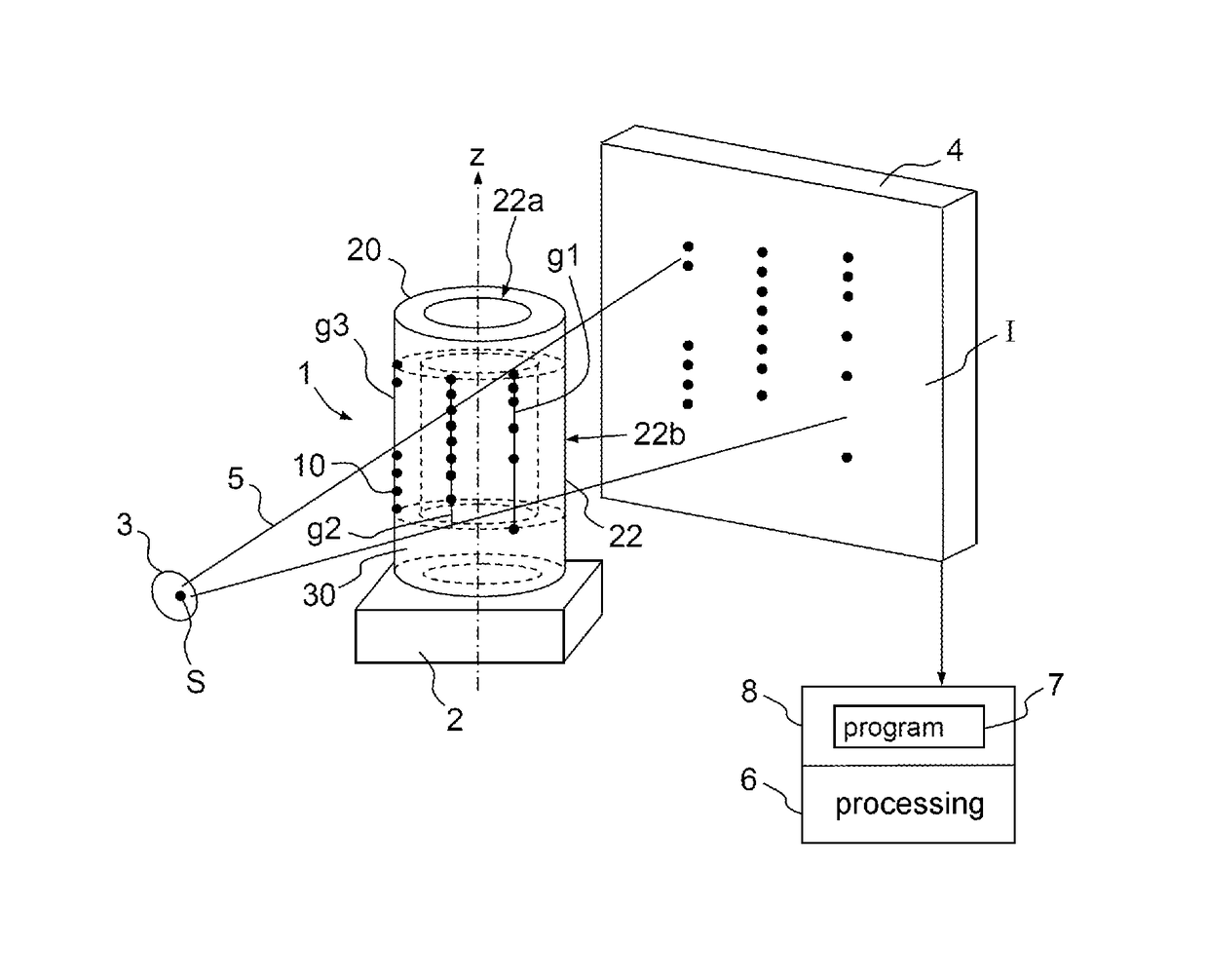
[0043]FIG. 1 shows an x-ray imaging device. This imaging device comprises an x-ray source 3 comprising a focal point S and a planar detector 4. The imaging device advantageously comprises a device (not shown) allowing the source 3 and the planar detector 4 to be moved with respect to a holder 2 intended to receive an object to be imaged.

[0044]The calibrating test pattern 1 according to the invention is thus interposed between an x-ray source 3 and the planar detector 4. It is stationary with respect to the holder 2. The calibrating device also comprises a processing device 6 that is configured to implement at least one processing method contained in a program 7 stored in a program memory 8. The test pattern 1 comprises markers 10. Advantageously, a program containing a processing method allowing geometric characteristics of the imaging device to be calculated from the association between projections of the markers of the test pattern in respective 2D projections of the test pattern ...


PUM

PropertyMeasurementUnit
sizeaaaaaaaaaa
lengthaaaaaaaaaa
energyaaaaaaaaaa

Abstract

A test pattern geometrically calibrates an x-ray imaging device to generate three-dimensional images of an object by reconstruction based on two-dimensional projections of the object, the calibrating test pattern comprising a volume support with markers having a radiological absorbance providing contrast to the volume support, the markers distributed in a three-dimensional pattern, in subsets substantially in parallel respective straight lines wherein sequences of cross-ratios are constructed from the respective subsets of markers. Each sequence of cross-ratios comprises a single cross-ratio for each quadruplet of markers in which quadruplet the markers are ordered depending on rank number of respective markers along the straight line they are aligned in a predefined first direction, the order being common to all cross-ratios. When a subset of markers comprises at least five markers, the order of the cross-ratios in the respective sequences of cross-ratios is defined by a rule common to all sequences of cross-ratios.

Description

CROSS-REFERENCE TO RELATED APPLICATION[0001]This application claims priority to foreign French patent application No. FR 1501892, filed on Sep. 11, 2015, the disclosure of which is incorporated by reference in its entirety.FIELD OF THE INVENTION[0002]The present invention relates to a device for geometric calibration of an x-ray imaging device. It more particularly relates to imaging devices the detector of which is two-dimensional, i.e. substantially planar. Imaging devices conventionally comprise an x-ray source and a two-dimensional detector. The x-rays are attenuated by a body to be imaged. The remaining energy is sensed by the detector and is converted into signals so as to produce a radiological image. The radiological image is a two-dimensional (2D) image (or projection) of an object deployed in a three-dimensional (3D) space interposed between the x-ray source and the two-dimensional detector. Conventionally, the x-ray source and the detector are installed on a device allowi...

Claims


Application Information

Patent Timeline
Patent Type & Authority Patents(United States)
IPC IPC(8): G01N23/04A61B6/03A61B6/00
CPCG01N23/04A61B6/032A61B6/584A61B6/583G01N2223/303
Inventor BERNARD, GUILLAUMEMURIENNE, ALBERT
Owner THALES SA
Why Eureka
Try Eureka