Object information extraction apparatus, object information extraction program, and object information extraction method

a technology of object information and extraction method, which is applied in the field of object information extraction apparatus, object information extraction program, and object information extraction method, can solve the problems of difficult to extract information of face details, inconvenient extraction of object information, and object imaged in the upper portion of the image is not suitable for object information extraction,

Active Publication Date: 2018-11-06
NEC CORP
View PDF13 Cites 0 Cited by
  • Summary
  • Abstract
  • Description
  • Claims
  • Application Information

AI Technical Summary

Benefits of technology

[0009]In the case of the above-described example, larger the object is imaged, more suitable the object is for extraction of the object information since the object information extraction apparatus can extract more information. For example, various pieces of information such as a shape of eyes or a nose can be accurately extracted from a largely imaged face. Therefore, an object imaged in a lower portion of an image is suitable for extraction of the object information. However, the object imaged in the lower portion is imaged in the smaller number of images since an amount of motion of the object is large. Therefore, an existing object information extraction apparatus, which extracts object information from the object in the image, extracts at a lower frequency the object information from the object in the lower portion of the image that is inherently suitable for extraction of the object information.
[0016]According to the present invention, it is possible to provide an object information extraction apparatus, an object information extraction program, and an object information extraction method with which necessary object information is reliably acquired.

Problems solved by technology

However, for each object in the image, ease of extraction of the object information is not equal.
However, the object imaged in the lower portion is imaged in the smaller number of images since an amount of motion of the object is large.
On the other hand, the object imaged in an upper portion of the image is not suitable for extraction of the object information.
For example, since a face of a person imaged in the upper portion of the image is small in the image, it is difficult to extract information of details of the face.
However, the object imaged in the upper portion is imaged in a lot of images since an amount of motion of the object is small.
Therefore, the existing object information extraction apparatus frequently extracts the object information from the object moving in the upper portion of the image that is not inherently suitable for extraction of the object information.
In this case, since an existing object information extraction apparatus extracts the object information from a large number of objects imaged in the image, a process of extracting the object information takes a lot of time.
As a result, an opportunity to extract the object information from an object suitable for feature-value extraction due to being largely imaged in the image is reduced, and necessary object information cannot be reliably acquired.

Method used


Image

  • Object information extraction apparatus, object information extraction program, and object information extraction method
  • Object information extraction apparatus, object information extraction program, and object information extraction method
  • Object information extraction apparatus, object information extraction program, and object information extraction method

Examples


exemplary embodiment 1

[Exemplary Embodiment 1]

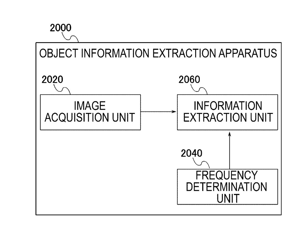
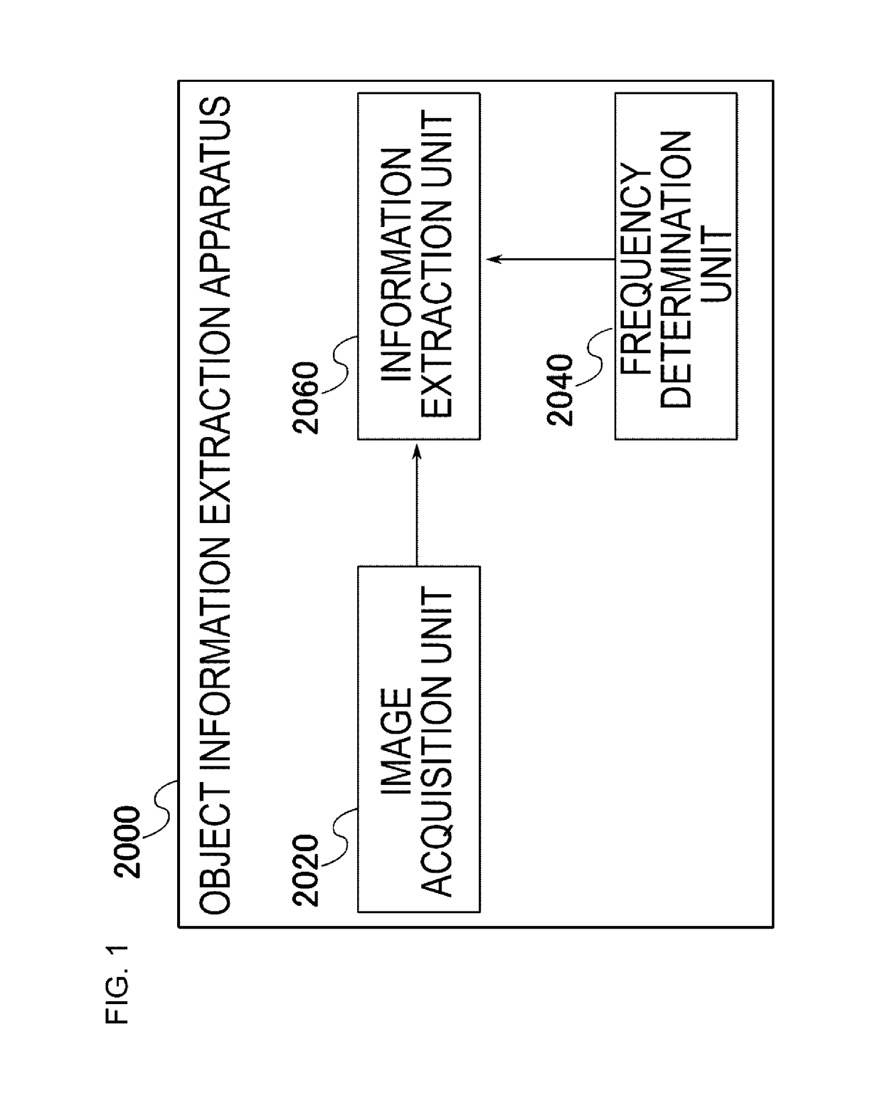
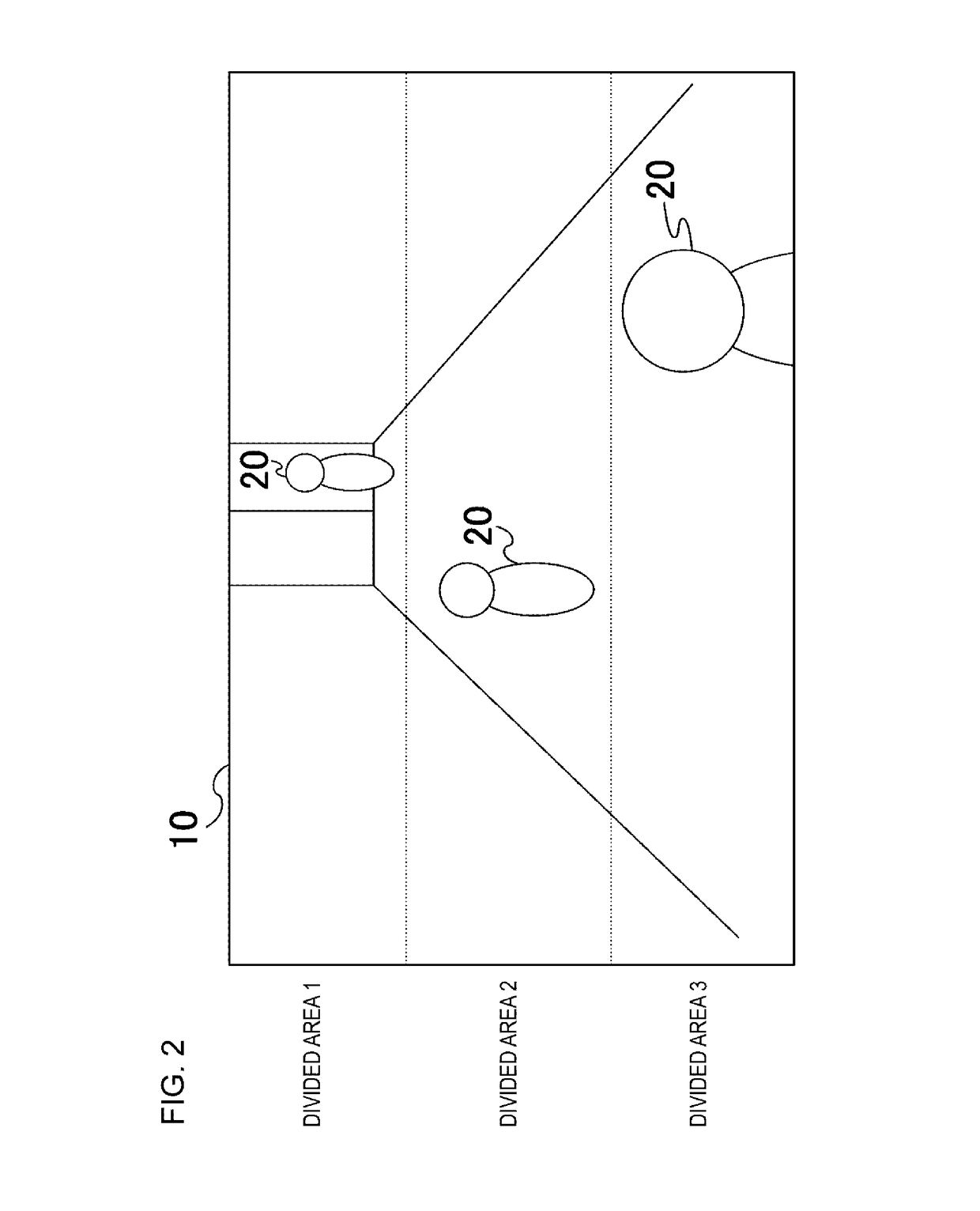
[0043]The object information extraction apparatus 2000 of this exemplary embodiment uses, as a partial area, a divided area that is each area obtained by dividing the image acquired by the image acquisition unit 2020 in one or more positions.

[0044]For example, the object information extraction apparatus 2000 of this exemplary embodiment separates each image into divided areas, as in an image 10 illustrated in FIG. 2. In FIG. 2, a dotted line is a line separating the divided areas. The image 10 is vertically divided into 3 areas, and divided area 1, 2 and 3 are divided areas. Each object 20 is an object imaged in the image 10.

[0045]The frequency determination unit 2040 of this exemplary embodiment acquires a frequency index shown for each-described divided area. Hereinafter, the frequency index shown for each divided area is referred to as a divided area frequency index. Also, the frequency determination unit 2040 generates the frequency information for each d...

exemplary embodiment 2

[Exemplary Embodiment 2]

[0075]In this exemplary embodiment, the same functional units as in Exemplary Embodiment 1 have the same functions as Exemplary Embodiment 1 unless particularly mentioned.

[0076]The object information extraction apparatus 2000 of this exemplary embodiment deals with an individual area representing the object in the image as the above-described partial area. For example, in the case of an image illustrated in FIG. 6, the object information extraction apparatus 2000 deals with each object 20 as a partial area. FIG. 6 illustrates an image obtained by photographing a state in which a person moves through a passage.

[0077]The frequency determination unit 2040 of this exemplary embodiment acquires an amount of motion of each object as a frequency index of the object. Also, the frequency determination unit 2040 calculates a frequency index based on the acquired amount of motion of each object (hereinafter, motion amount frequency index). Here, the frequency determinat...

exemplary embodiment 3

[Exemplary Embodiment 3]

[0101]The object information extraction apparatus 2000 in this exemplary embodiment sets an individual area representing each object as the partial area.

[0102]The frequency determination unit 2040 in this exemplary embodiment acquires an amount of motion of each object. Also, the frequency determination unit 2040 calculates a motion amount frequency index for each object. The frequency determination unit 2040 further acquires the divided area frequency index of each divided area obtained by dividing each image. Also, the frequency determination unit 2040 calculates the frequency for each object based on the motion amount frequency index of the object and the divided area frequency index of the divided area including the object.

[0103]For example, the frequency determination unit 2040 calculates the motion amount frequency index from the acquired motion amount of the object using Equation 1, similarly to Exemplary Embodiment 2. Further, the frequency determinat...


PUM


Abstract

An object information extraction apparatus (2000) includes an image acquisition unit (2020), a frequency determination unit (2040), and an information extraction unit (2060). The image acquisition unit (2020) acquires a plurality of images corresponding to a predetermined unit time of a video. The frequency determination unit (2040) generates frequency information for each of a plurality of partial areas included in each of a plurality of images. The information extraction unit (2060) extracts information of an object included in each partial area from each image corresponding to the number indicated by the frequency information for each partial region among a plurality of images corresponding to a predetermined unit time for each partial area.

Description

[0001]This application is a National Stage Entry of PCT / JP2013 / 002069 filed on Mar. 27, 2013, which claims priority from Japanese Patent Application 2012-209111 filed on Sep. 24, 2012, the contents of all of which are incorporated herein by reference, in their entirety.TECHNICAL FIELD[0002]The present invention relates to an object information extraction apparatus, an object information extraction program, and an object information extraction method.BACKGROUND ART[0003]An apparatus extracting information of an object such as a person or a car imaged by a monitoring camera or the like (hereinafter referred to as object information) has been developed. Here, the object refers to an object such as a person, a car, or an animal. Further, the object information is information indicating a position or a shape of the object or information indicating a feature-value of the object. The feature-value of the object is a value indicating a feature such as a face, clothing or the like of a perso...

Claims


Application Information

Patent Timeline
Patent Type & Authority Patents(United States)
IPC IPC(8): G06K9/46G06K9/52G06K9/00G06V10/44
CPCG06K9/4604G06K9/522G06K9/00785G06K9/00221G06V40/16G06V20/54G06V10/44G06V10/431
Inventor OAMI, RYOMA
Owner NEC CORP
Why Eureka
Try Eureka