Planted pole reinforcement methods

a technology for planting poles and reinforcement methods, which is applied in the direction of building repairs, building types, constructions, etc., can solve the problems of common groundline damage to planted utility poles, loss of groundline strength, and failure of the structure, so as to prevent the loss of flowable composition, facilitate the restoration of groundline strength capacity, and improve the effect of structural aesthetics

Active Publication Date: 2019-03-12
LOGSYS POWER SERVICES PTY LTD
View PDF19 Cites 1 Cited by
  • Summary
  • Abstract
  • Description
  • Claims
  • Application Information

AI Technical Summary

Benefits of technology

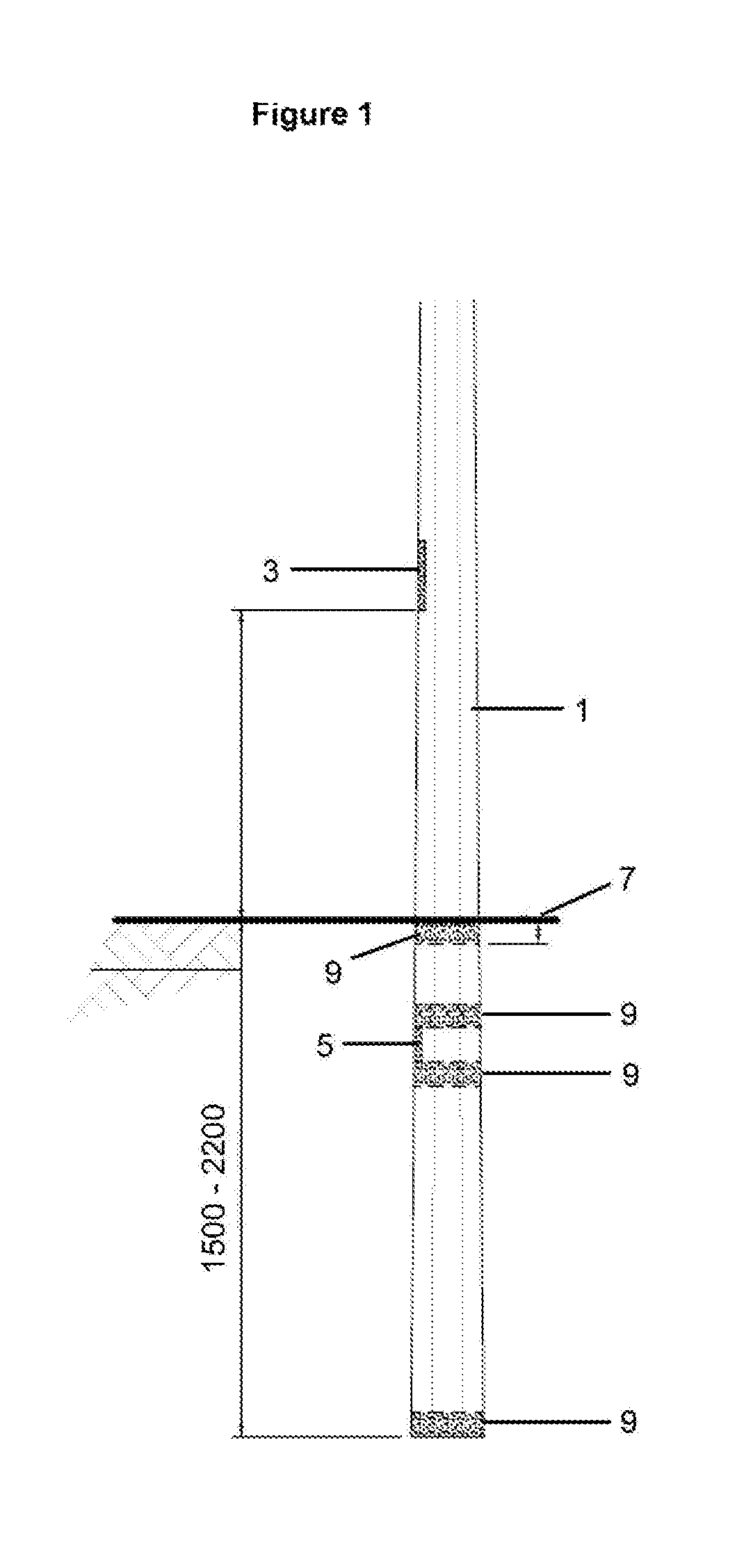
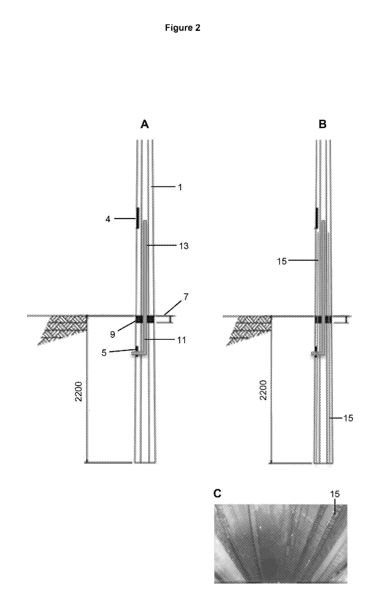
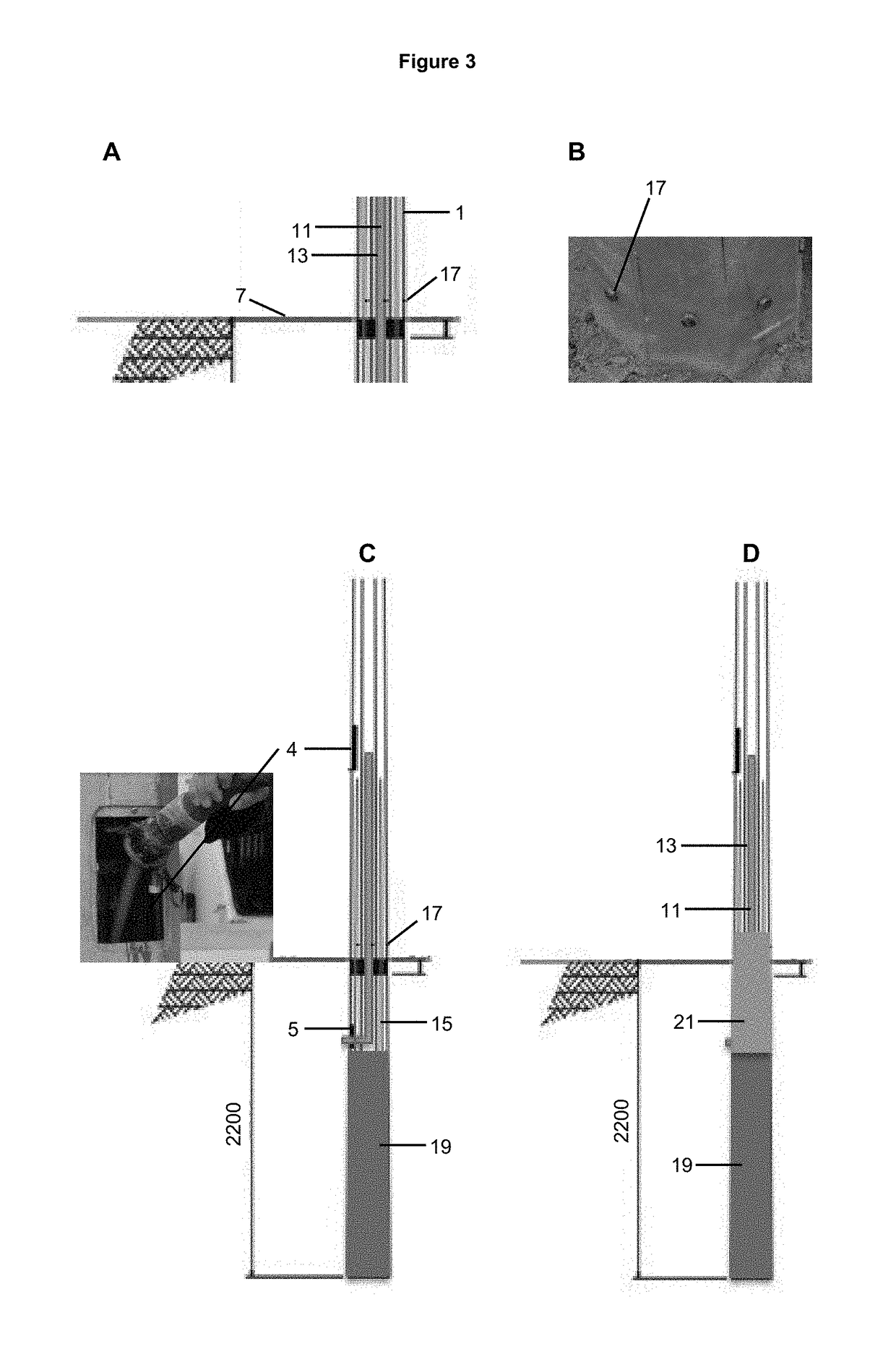
[0021]The composition is delivered through a hole, and preferably an access hole, in the side of the planted pole to be reinforced. Delivery of the flowable composition may be through use of a variety of different means and methods known in the art. In a preferred method, the flowable composition is pumped through a hose which is directed into the hollow through the access hole. The flowable composition is preferably pumped through the hose into the hollow of the planted pole at a slow rate so as to avoid the formation of air pockets in the composition. The flowable composition pumped into the hollow fills the base of the planted pole below the ground line and preferably up to a pre-determined height above the groundline which reinforces the planted pole in the region potentially most affected by, for example, corrosion for metal poles, or damage to other types of hollow planted poles. Preferably, the composition fills the hollow in the base of the planted pole to a minimum height of approximately 200 mm above the groundline. The height the composition fills the hollow in the base of the planted pole above the groundline may depend on road safety or other regulations. For example, maximum heights for reinforcement above the groundline may be specified by local authorities to prevent worse outcomes for a vehicle impacting a pole. Therefore, in a preferred embodiment, the composition fills the hollow in the base of the planted pole to a height of approximately 200 mm above the groundline.
[0024]For non-circular planted poles having multiple sides, attachment means are preferably inserted or drilled through the wall of the planted pole into at least one side. More preferably, attachment means are inserted or drilled into the exterior surface of each side of the wall of a non-circular planted pole. Two or more attachment means inserted or drilled into the wall of the planted pole, whether round, or having multiple sides, may be at the same height of the planted pole or at different heights. There may also be more than one ‘row’ of two or more attachment means inserted or drilled into the wall of the planted pole at the same height. Multiple attachment means and multiple ‘rows’ of attachment means will provide an advantage of greater attachment strength between the planted pole and set substantially non-flowable composition, particularly for larger planted poles of metal.
[0025]Prior to reinforcing a hollow planted pole according to a method of the invention, the hollow is preferably cleaned before the flowable composition is delivered. Thus, the method of the invention preferably includes a prior step of cleaning the hollow of a planted pole in the vicinity of the base, for example, between the access hole and the base of the pole. More preferably, the hollow is cleaned with compressed air or water. Cleaning with water has the added benefit of assisting to cure concrete or grout, and the wetting of the soil at the base of the pole prevents excessive extraction of moisture from wet concrete or grout.
[0027]The method of the invention is preferably carried out on a hollow planted pole for the benefit that the pole can be reinforced without removing it from the ground. However, the method of the invention could also be carried out on a pole that is not planted in the ground, for example, because it has been removed from the ground for repair, or has not yet been planted in the ground, wherein the base will need to be covered to prevent loss of flowable composition before it has set.
[0028]The method of the invention assists the reinstatement of the groundline strength capacity of a hollow planted pole and ultimately offers a life extension to the pole at a fraction of the cost of repair without compromising the aesthetic features of the structure.

Problems solved by technology

Unfortunately, planted utility poles of metal commonly experience groundline damage and loss of groundline strength as a result of contact with soils, moisture and oxygen.
Any significant loss in strength capacity can result in the failure of the structure.

Method used


Image

  • Planted pole reinforcement methods
  • Planted pole reinforcement methods
  • Planted pole reinforcement methods

Examples


Embodiment Construction

[0040]Those skilled in the art will appreciate that the invention described herein is susceptible to variations and modifications other than those specifically described. The invention includes all such variation and modifications. The present invention is also not to be limited in scope by any of the specific embodiments described herein. These embodiments are intended for the purpose of exemplification and illustration only. Functionally equivalent apparatus and methods are clearly within the scope of the invention as described herein. The invention also includes all of the features and / or steps referred to or indicated in the specification, individually or collectively and any and all combinations or any two or more of the features and / or steps.

[0041]Each document, reference, patent application or patent cited in this text is expressly incorporated herein in their entirety by reference, which means that it should be read and considered by the reader as part of this text. That the...


PUM


Abstract

A method is described for reinforcing to extend the life of a planted pole, including a metal planted utility pole at risk of, or damaged by corrosion. The method comprising delivering a flowable composition into the hollow of the planted pole, the flowable composition being capable of setting in the hollow at least proximate to the groundline to form a substantially non-flowable composition when set; the set composition comprising reinforcement supports, and being attached to the pole to provide additional support for the planted pole at least proximate to the groundline.

Description

TECHNICAL FIELD[0001]The present invention relates to methods for reinforcing hollow planted poles and in particular, hollow planted utility poles of metal.BACKGROUND ART[0002]In cities around the world, there has been a growing interest in replacing aging timber electric utility distribution poles and light poles with steel poles. Using galvanized steel utility poles is regarded as having several significant environmental benefits over timber including lower levels of greenhouse gas and aerosol emissions associated with global climate change; a lower burden on critical energy resources; reduced impacts on the habitats of many threatened and endangered species; and reduced impacts associated with hazardous emissions and wastes.[0003]Steel utility poles are also regarded as having a number of other clear advantages over competing materials, for example, treated wood and concrete, including: ease of installation, fabrication with uniform dimensions, reliability, durability, impervious...

Claims


Application Information

Patent Timeline
Patent Type & Authority Patents(United States)
IPC IPC(8): E04H12/08E04H12/22E04G23/02
CPCE04H12/2292E04H12/08E04G23/0218
Inventor SPANGENBERG, DAVID CHARLES
Owner LOGSYS POWER SERVICES PTY LTD
Why Eureka
Try Eureka