Organic electroluminescent element, illumination device, and display device

a technology of electroluminescent elements and illumination devices, applied in semiconductor devices for light sources, lighting and heating apparatuses, planar light sources, etc., can solve the problem that light cannot be effectively propagated outside where light is perceived, and achieve excellent light emitting properties and high light-outcoupling efficiency

Active Publication Date: 2018-01-16
SAMSUNG DISPLAY CO LTD
View PDF35 Cites 0 Cited by
  • Summary
  • Abstract
  • Description
  • Claims
  • Application Information

AI Technical Summary

Benefits of technology

[0008]The present disclosure aims to provide an organic EL element, an illumination device, and a display device which have high light-outcoupling efficiency.
[0012]In the organic electroluminescent element of the present disclosure, since the light emitting layer has the birefringence property and the at least one light-outcoupling structure is provided closer to the light-outcoupling side than the first electrode, more of light from the light emitting layer can be extracted outside. As a result, the organic electroluminescent element, the illumination device, and the display device which have the high light-outcoupling efficiency and an excellent light emitting property can be obtained.

Problems solved by technology

The reason for this is that light cannot be effectively propagated outside where light is perceived, due to total reflection at an interface between materials with different refractive indices, absorption of light by a material, and the like.
However, even in the organic EL element employing methods such as the above disclosed in the literature, it can hardly be said that the light-outcoupling efficiency is sufficiently improved, and thus a structure which can improve the light-outcoupling efficiency even further is in demand.

Method used


Image

  • Organic electroluminescent element, illumination device, and display device
  • Organic electroluminescent element, illumination device, and display device
  • Organic electroluminescent element, illumination device, and display device

Examples


Embodiment Construction

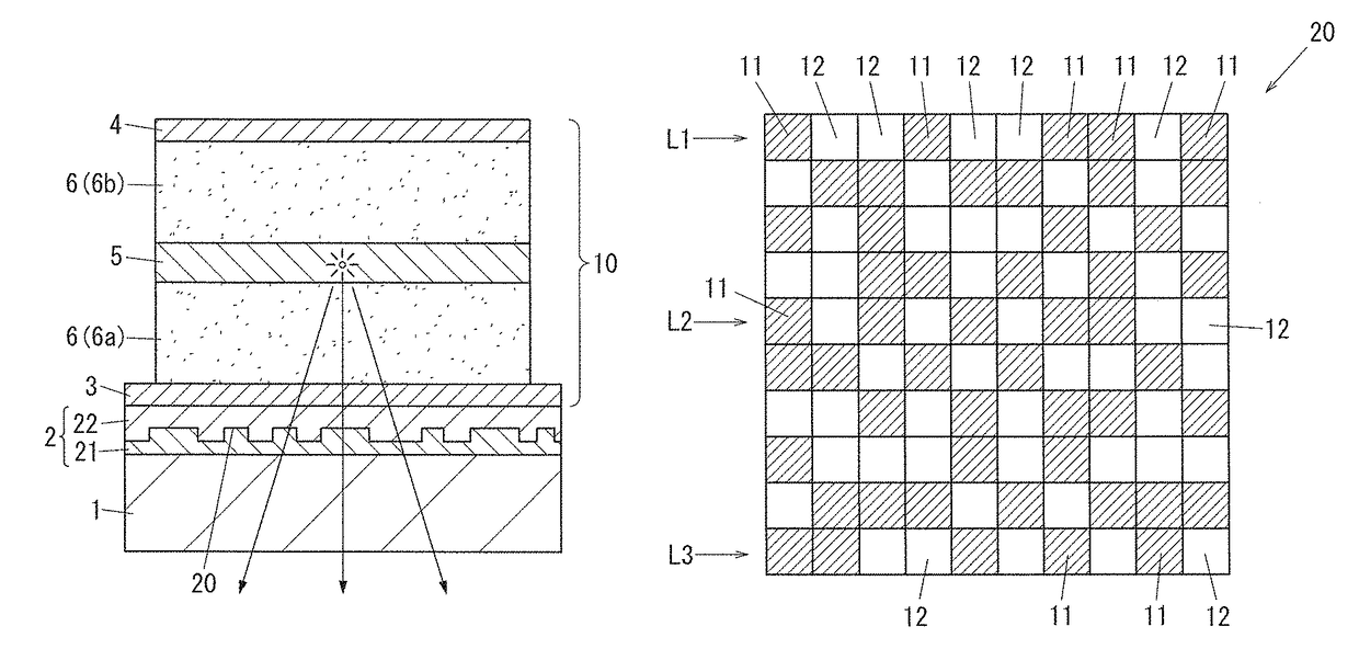
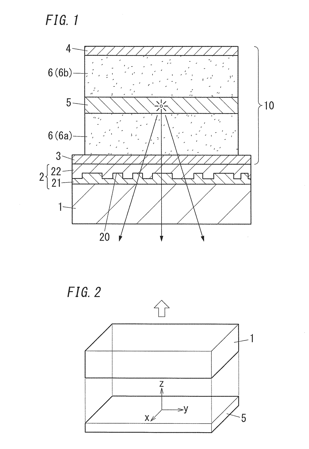
[0043]An organic electroluminescent element (organic EL element) is disclosed. The organic electroluminescent element includes: a light transmissive substrate 1; a light emitting stack 10 including a first electrode 3 being light transmissive, a light emitting layer 5, and a second electrode 4 which are arranged in this order from the light transmissive substrate 1; and at least one light-outcoupling structure 2 which has an uneven structure 20. The light emitting layer 5 has a birefringence property which exhibits a higher refractive index in a direction parallel to a surface of the light transmissive substrate 1 than a refractive index in a direction perpendicular to the surface of the light transmissive substrate 1. The at least one light-outcoupling structure 2 is provided closer to a light-outcoupling side, defined as an opposite side of the first electrode 3 from the light emitting layer 5, than the first electrode 3. The uneven structure 20 includes a plurality of protrusions...


PUM

PropertyMeasurementUnit
refractive indexaaaaaaaaaa
refractive indicesaaaaaaaaaa

Abstract

This organic electroluminescent element includes: a light transmissive substrate; a light emitting stack including a first electrode, a light emitting layer, and a second electrode; and at least one light-outcoupling structure which has an uneven structure. The light emitting layer has a birefringence property with a higher refractive index in a direction parallel to a surface of the light transmissive substrate than a refractive index in a direction perpendicular to the surface of the light transmissive substrate. The uneven structure includes a plurality of protrusions which are individually allocated to some of planar matrix-like sections, and with regard to unit regions consisting of same number of sections of the planar matrix-like sections, a ratio of an area of one or more of the plurality of protrusions in a unit region is substantially constant in each unit region.

Description

TECHNICAL FIELD[0001]Organic electroluminescent elements, illumination devices using same, and display devices using same are disclosed. More particularly, organic electroluminescent elements including at least one light-outcoupling structure are disclosed.BACKGROUND ART[0002]In a generally known structure of an organic electroluminescent element (hereinafter referred to as “organic EL element”), a light emitting stack including an anode, a hole transport layer, a light emitting layer, an electron injection layer, and a cathode are stacked on a surface of a substrate which is light transmissive. In such organic EL element, light is produced in the light emitting layer when voltage is applied between the anode and the cathode, and produced light is extracted outside through the electrode and the substrate which are light transmissive.[0003]Generally, light-outcoupling efficiency is about 20 to 30% in an organic EL element, meaning that light which cannot effectively contribute to lig...

Claims


Application Information

Patent Timeline
Patent Type & Authority Patents(United States)
IPC IPC(8): H01L51/52H01L51/50H01L51/00
CPCH01L51/5268H01L51/5056H01L51/5072H01L51/5092H01L51/5275H01L51/5293H01L51/5088H01L51/0037H10K85/1135H10K50/854H10K50/868H10K50/858F21Y2105/16F21Y2115/15H10K50/814H10K59/10H10K50/15H10K50/16H10K50/17H10K50/171
Inventor YAMAE, KAZUYUKIINADA, YASUHISAHASHIYA, AKIRA
Owner SAMSUNG DISPLAY CO LTD
Why Eureka
Try Eureka