

Drip filter head and method
a filter head and drip filter technology, applied in beverage vessels, household appliances, kitchen equipment, etc., can solve the problems of bitter beverages, overextraction, and slowed water flow through known drip filter devices, so as to reduce manufacturing complexity, reduce cost, and facilitate cleaning
- Summary
- Abstract
- Description
- Claims
- Application Information
AI Technical Summary
Benefits of technology
Problems solved by technology
Method used
Image

Examples
example 1
Preparation of a Beverage Using a Drip Filter Head of the Invention
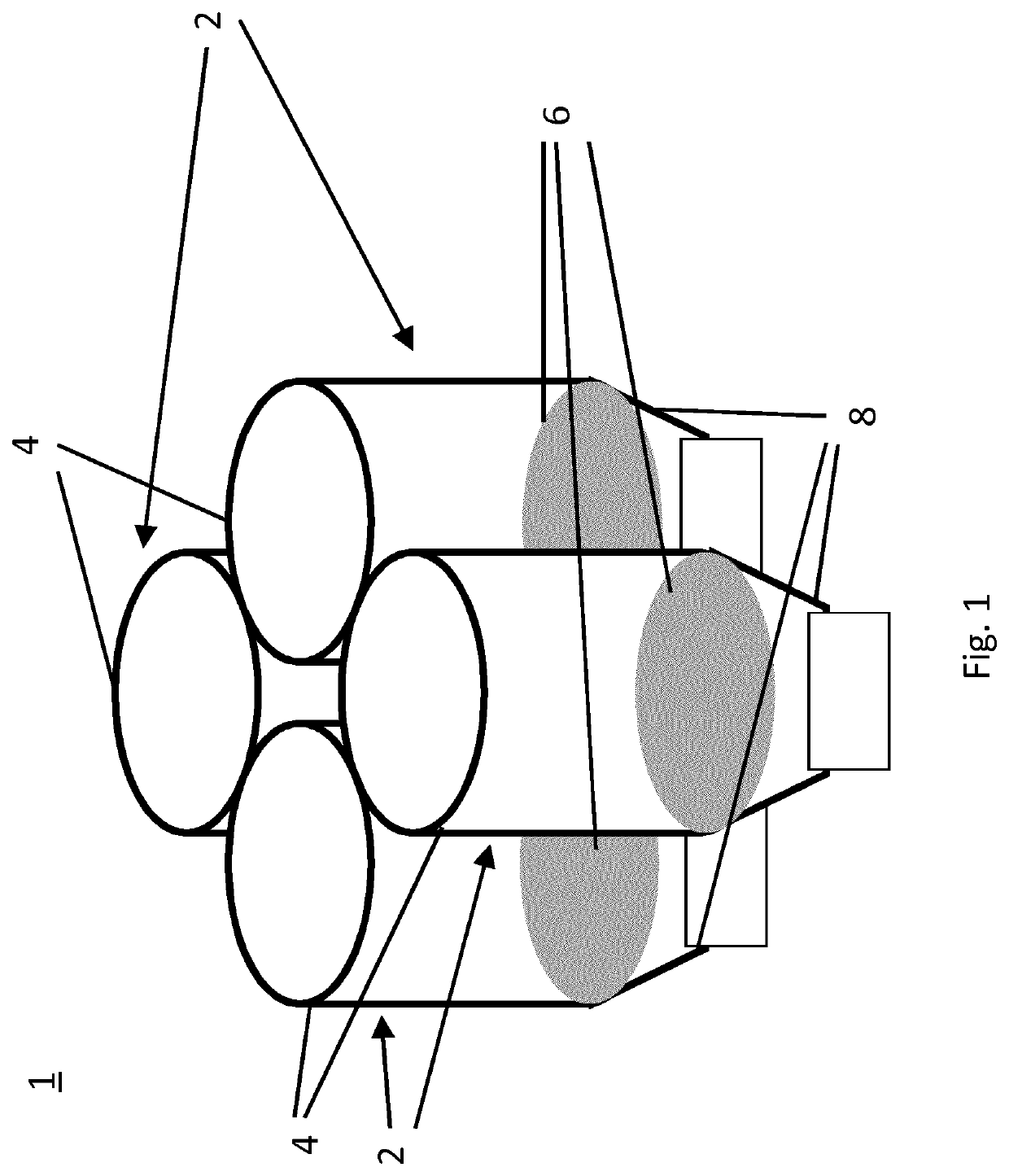
[0113]A beverage was prepared using the drip filter head (1) of FIG. 1 by the following steps:[0114]a) Each extraction unit (2) contained a standard coffee filter paper (6) shaped to fit flat across the full diameter of each extraction chamber (4) and the drip filter head (1) was positioned over a container;[0115]b) 12 g of roast and ground coffee (Aroma Rood® produced by Jacobs Douwe Egberts) was loaded into each of the four extraction chambers (4) on top of the filter (6);[0116]c) Each extraction chamber (4) was then filled with 234 ml of water heated to 80-100° C. and the beverage extract allowed to drip through the head (1) under gravity, and;[0117]d) The beverage extract from the drip filter head (1) was collected in a single container.
[0118]The time taken from first addition of water to the drip filter head (1) until the flow of beverage extract from the drip filter head (1) had substantially stopped was 4 minu...
example 2
Preparation of a Beverage Using Enhanced Extraction Units
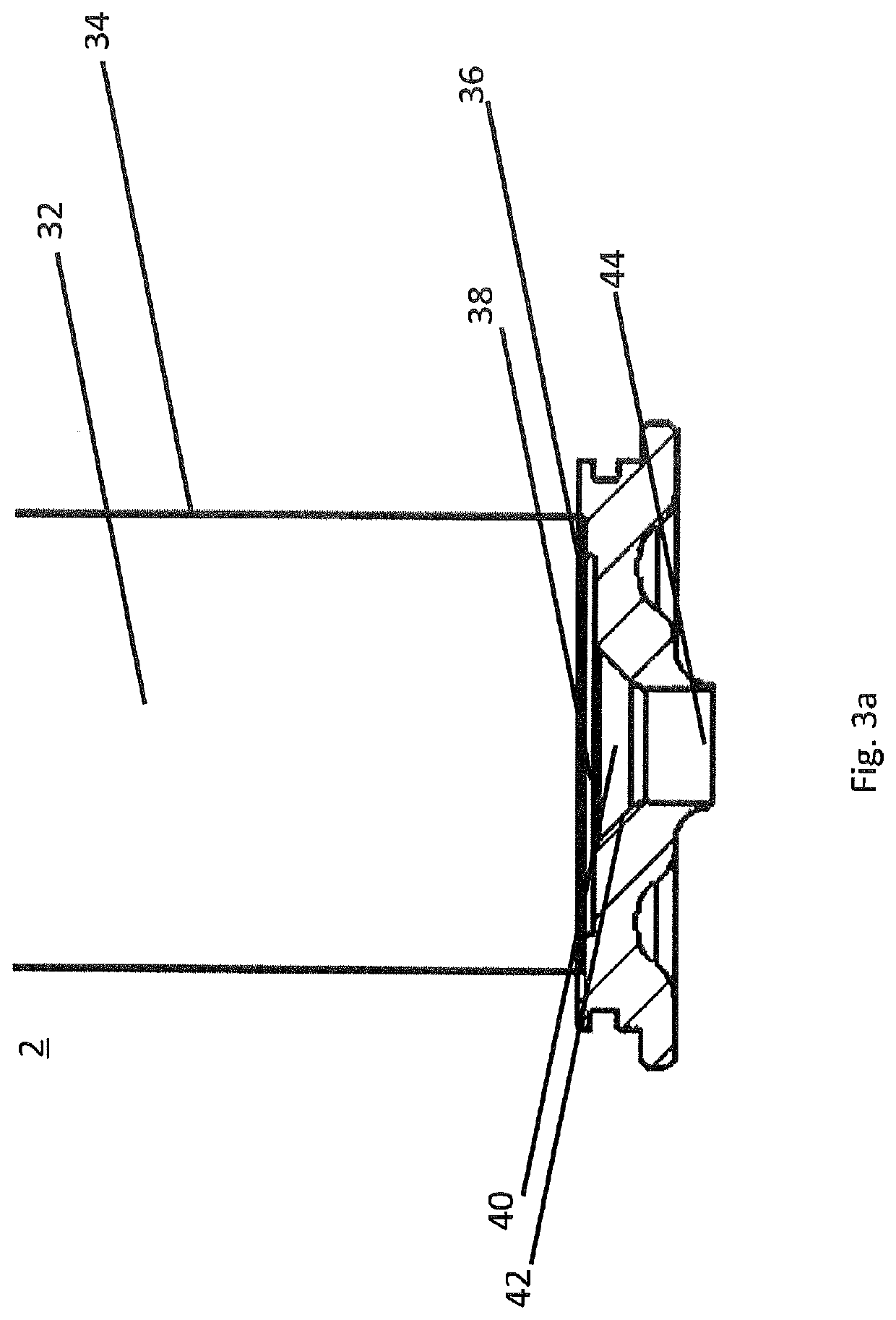
[0119]A beverage was prepared using the drip filter head (1) of FIG. 1 comprising the extraction units (2) of FIG. 3a by the following steps:[0120]a) Each of the four extraction chambers (32) was loaded with 12 g of roast and ground coffee (Aroma Rood®, produced by Jacobs Douwe Egberts), each extraction unit (2) fitted with a Senseo® chocolate filter paper, code UPC05A and the drip filter head (1) supported above a beverage container;[0121]b) 234 ml of water heated to 80-100° C. was then added at a rate of 2.6 ml / sec to each extraction chamber at a steady rate over 1 minute 30 seconds at the same time. During this time the volume of water in each extraction chamber (32) built to a maximum i.e. the flow rate of heated water into each extraction chamber (32) was the same as the flow rate of the beverage extract from each outlet (44); and[0122]c) After the addition of water stopped, the drip filter head (1) was then left to drain...
example 3
Preparation of a Beverage Using Enhanced Extraction Units within an Appliance
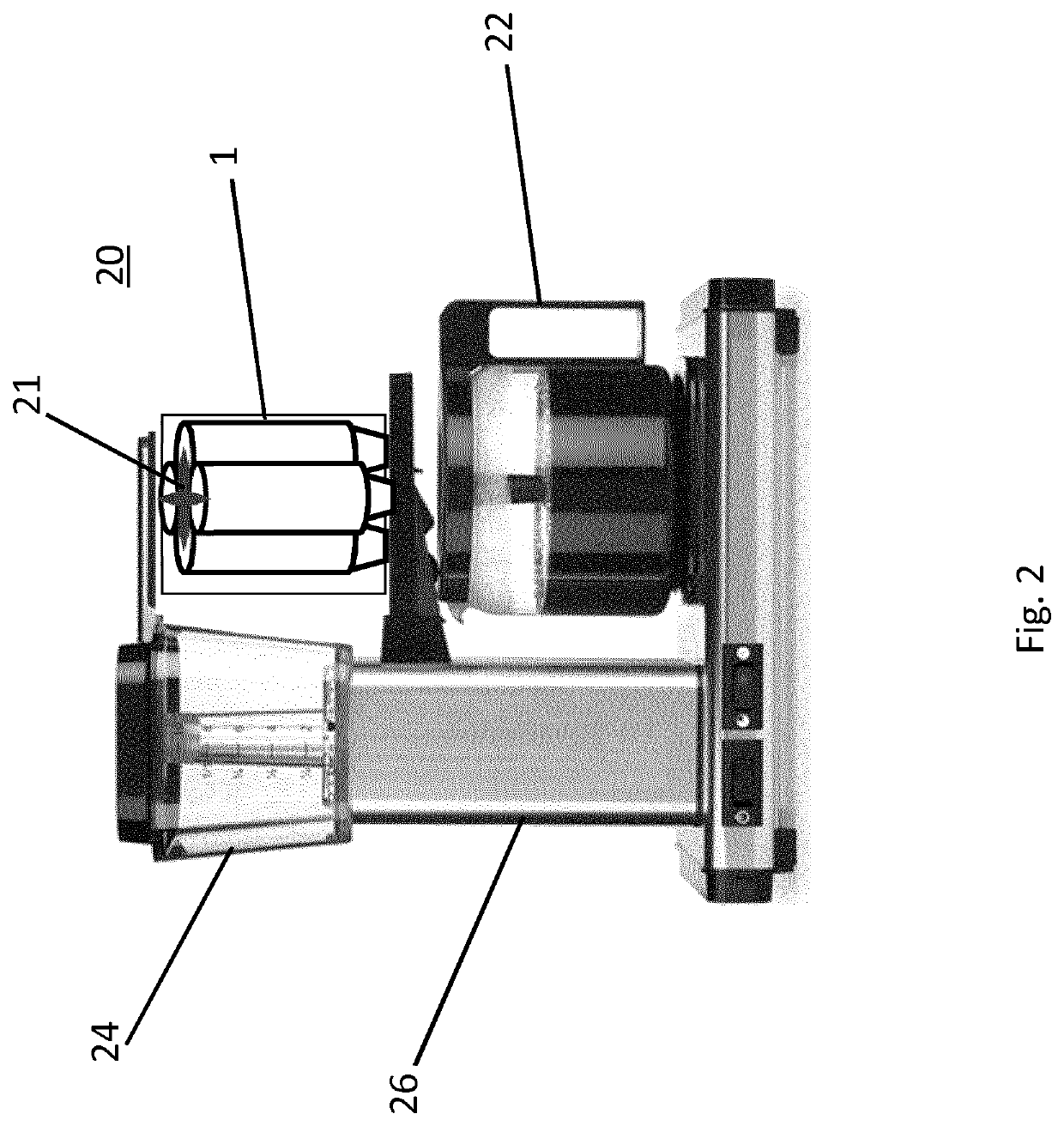
[0132]A beverage extract was prepared using a by loading the drip filter head (1) of FIG. 1, comprising the extraction units of FIG. 3a, into an Excellent lOSN drip filter appliance manufactured by Douwe Egberts to create the beverage preparation apparatus (20) of FIG. 2 by the following steps:[0133]a) 12 g ofroast and ground coffee was added to each extraction chamber (32) of the drip filter head (1);[0134]b) Cold water was added to the water reservoir (24) of the apparatus (20); and[0135]c) The apparatus (20) was switched on to provide a steady flow of 234 ml of hot water, to each of the four extraction chambers, at a rate of 2.6 ml / sec over 1 minute 30 seconds and the beverage extract collected from the outlets (44).
[0136]The beverage extract flow rate was identical to that of Example 2 and the beverage had the same profile under sensory analysis as that of Example 2. The beverage preparation ceased afte...
PUM
 Abstract
Description
Claims
Application Information