Ceiling triggered spring clip for lighting module install

a technology of installing a lighting module and a spring clip, which is applied in the direction of fixed installation, lighting and heating equipment, and support devices for lighting and heating, etc., can solve the problems of installer fatigue and the risk of falling to the installer, and achieve the effect of generating less installer fatigue, reducing installation time and reducing installation tim

Active Publication Date: 2018-11-13
AMP PLUS
View PDF10 Cites 39 Cited by
  • Summary
  • Abstract
  • Description
  • Claims
  • Application Information

AI Technical Summary

Benefits of technology

[0011]It is another objective of the present invention to provide a trigger-release-clip that may be installed into the receiving hole of the ceiling with only use of one hand of the installer.
[0012]It is another objective of the present invention to provide a trigger-release-clip that may be faster to use in installing lighting modules compared against existing lighting modules with spring clips.
[0013]It is another objective of the present invention to provide a trigger-release-clip that may be easier to use in installing lighting modules compared against existing lighting modules with spring clips.
[0014]It is another objective of the present invention to provide a trigger-release-clip that may generate less installer fatigue compared against existing lighting modules with spring clips.
[0015]It is another objective of the present invention to provide a trigger-release-clip that may be more efficient to use in installing lighting modules compared against existing lighting modules with spring clips.
[0016]It is yet another objective of the present invention to provide a trigger-release-clip that may be safer for the installer to use while the installer is working overhead and / or while the installer is on a ladder as compared against existing lighting modules with spring clips.

Problems solved by technology

Further, when the installer is installing multiple lighting modules and overhead, applying such constant pressure and using both hands to keep the spring clips open during install results in installer fatigue.
Also, because installation is generally overhead, ladders are often used, and use of two hands for lighting module install while on a ladder increase risk of falling to the installer.

Method used


Image

  • Ceiling triggered spring clip for lighting module install
  • Ceiling triggered spring clip for lighting module install
  • Ceiling triggered spring clip for lighting module install

Examples


Embodiment Construction

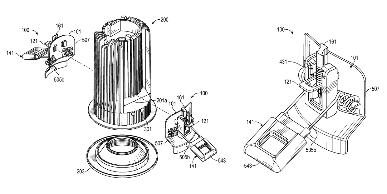
[0093]In the following discussion that addresses a number of embodiments and applications of the present invention, reference is made to the accompanying drawings that form a part thereof, where depictions are made, by way of illustration, of specific embodiments in which the invention may be practiced. It is to be understood that other embodiments may be utilized and changes may be made without departing from the scope of the invention.

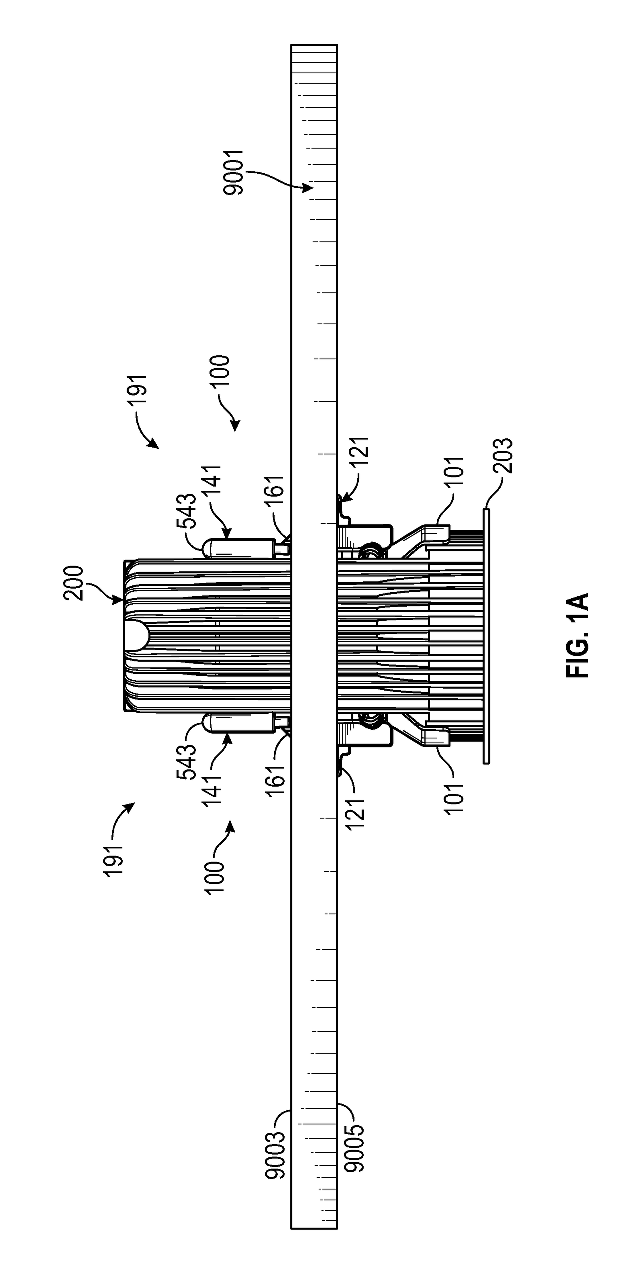
[0094]FIG. 1A may depict a pair of trigger-release-clips 100 mounted to a lighting module 200, wherein trigger-release-clips 100 may be used to mount lighting module 200 to a planar-member 9001, wherein the trigger-release-clips 100 may be in a pre-loaded configuration 191, shown from a cross-sectional side view through planar-member 9001.

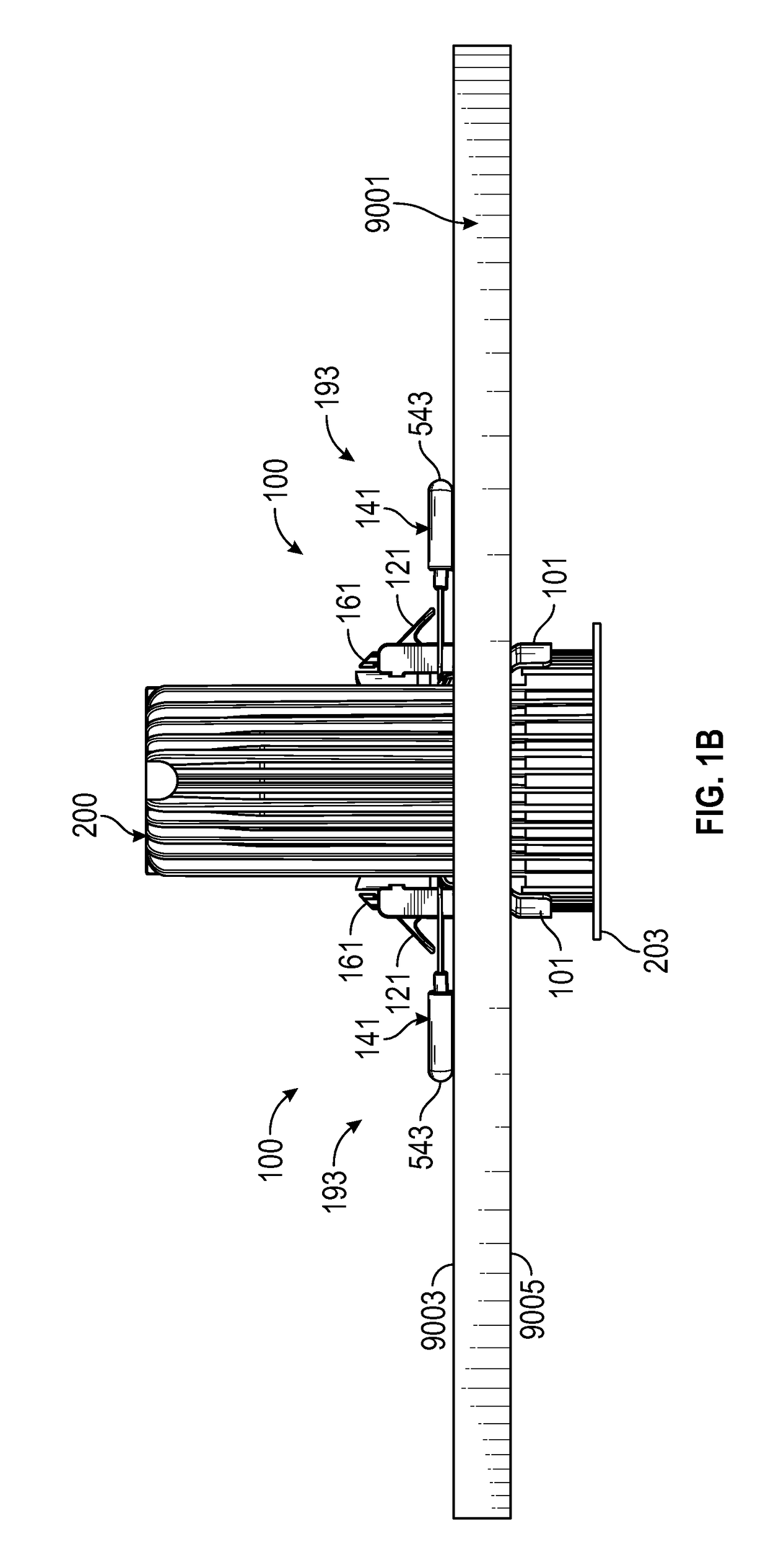
[0095]FIG. 1B may depict the pair of trigger-release-clips 100 mounted to lighting module 200, wherein trigger-release-clips 100 may be in a transitional configuration 193, shown from the same cross-sectional side v...


PUM


Abstract

A preloadable trigger-release-clip that may be ceiling triggered for lighting module installation is described, including systems and methods of use. The trigger-release-clip may include a base-plate, a trigger, a clip, and a stop. The base-plate may be a structural member that attaches to a lighting module. The trigger may be in communication with the base-plate. The clip, with a torsion-spring, may be in communication with the base-plate. The stop may be in communication with the trigger. In a pre-loaded configuration, the stop may be in an up position that prevents the clip from actuating. In a final configuration, the stop has been retracted into a down position by the trigger being depressed by a bottom of a ceiling that may allow the clip to actuate, such that a terminal end of the clip pivots to grab a top of the ceiling securing the lighting module to the ceiling.

Description

TECHNICAL FIELD OF THE INVENTION[0001]The present invention relates in general to torsion spring clips used to install lighting modules and more specifically to a pre-loadable open configuration trigger-spring-clip that may be ceiling triggered for lighting module install.COPYRIGHT AND TRADEMARK NOTICE[0002]A portion of the disclosure of this patent application may contain material that is subject to copyright protection. The owner has no objection to the facsimile reproduction by anyone of the patent document or the patent disclosure, as it appears in the Patent and Trademark Office patent file or records, but otherwise reserves all copyrights whatsoever.[0003]Certain marks referenced herein may be common law or registered trademarks of third parties affiliated or unaffiliated with the applicant or the assignee. Use of these marks is by way of example and should not be construed as descriptive or to limit the scope of this invention to material associated only with such marks.BACKG...

Claims


Application Information

Patent Timeline
Patent Type & Authority Patents(United States)
IPC IPC(8): F21V21/26F16B2/20F21V17/16F21S8/02
CPCF21V21/26F21V17/166F21S8/026F16B2/205F21V17/10F21V21/046F16B2/10F16B13/0808F16B9/07
Inventor COHEN, BRANDON
Owner AMP PLUS
Why Eureka
Try Eureka