Junction box with an integrated connection circuit

a junction box and integrated connection technology, applied in the direction of coupling devices, two-part coupling devices, electrical apparatus, etc., can solve the problems of tipped switches and outlets within the junction box, and achieve the effect of eliminating field wiring

Inactive Publication Date: 2019-01-01
REULMAN SR DAVID MARK
View PDF41 Cites 6 Cited by
  • Summary
  • Abstract
  • Description
  • Claims
  • Application Information

AI Technical Summary

Benefits of technology

[0015]It is an object of the junction box with an integrated connection circuit to eliminate field wiring by an electrician. This will no longer require an electrician to strip wires, and screw the stripped wired into outlets or switches. This also eliminates the extra length of wire that is folded and packed into the electrical outlet box. The folded, wrapped or bunched wire is often difficult to place in the junction box and can cause switches and outlets to be tipped and not flat within the junction box. This tipping is eliminated because each switch or outlet sits flush against the back of the junction box.
[0018]It is another object of the junction box with an integrated connection circuit to utilize proprietary light switches, duplex outlets and trim plates. The proprietary pieces allow for a smaller height, width and depth of the electrical junction box. This allows for new architectural options in the design of a house or for upgrades to an existing house with 110-volt electrical control and supply connections.
[0020]It is still another object of the junction box with an integrated connection circuit to eliminate the time-consuming labor for the installation. Instead of minutes to install an outlet or switch, an installer can set or replace a switch or outlet in seconds. Because all of the components have a standard configuration and alignment, the potential for a short or open circuit is virtually eliminated.

Problems solved by technology

The folded, wrapped or bunched wire is often difficult to place in the junction box and can cause switches and outlets to be tipped and not flat within the junction box.

Method used


Image

  • Junction box with an integrated connection circuit
  • Junction box with an integrated connection circuit
  • Junction box with an integrated connection circuit

Examples


Embodiment Construction

[0040]It will be readily understood that the components of the present invention, as generally described and illustrated in the drawings herein, could be arranged and designed in a wide variety of different configurations. Thus, the following more detailed description of the embodiments of the system and method of the present invention, as represented in the drawings, is not intended to limit the scope of the invention, but is merely representative of various embodiments of the invention. The illustrated embodiments of the invention will be best understood by reference to the drawings, wherein like parts are designated by like numerals throughout.

ITEM NUMBERS AND DESCRIPTION

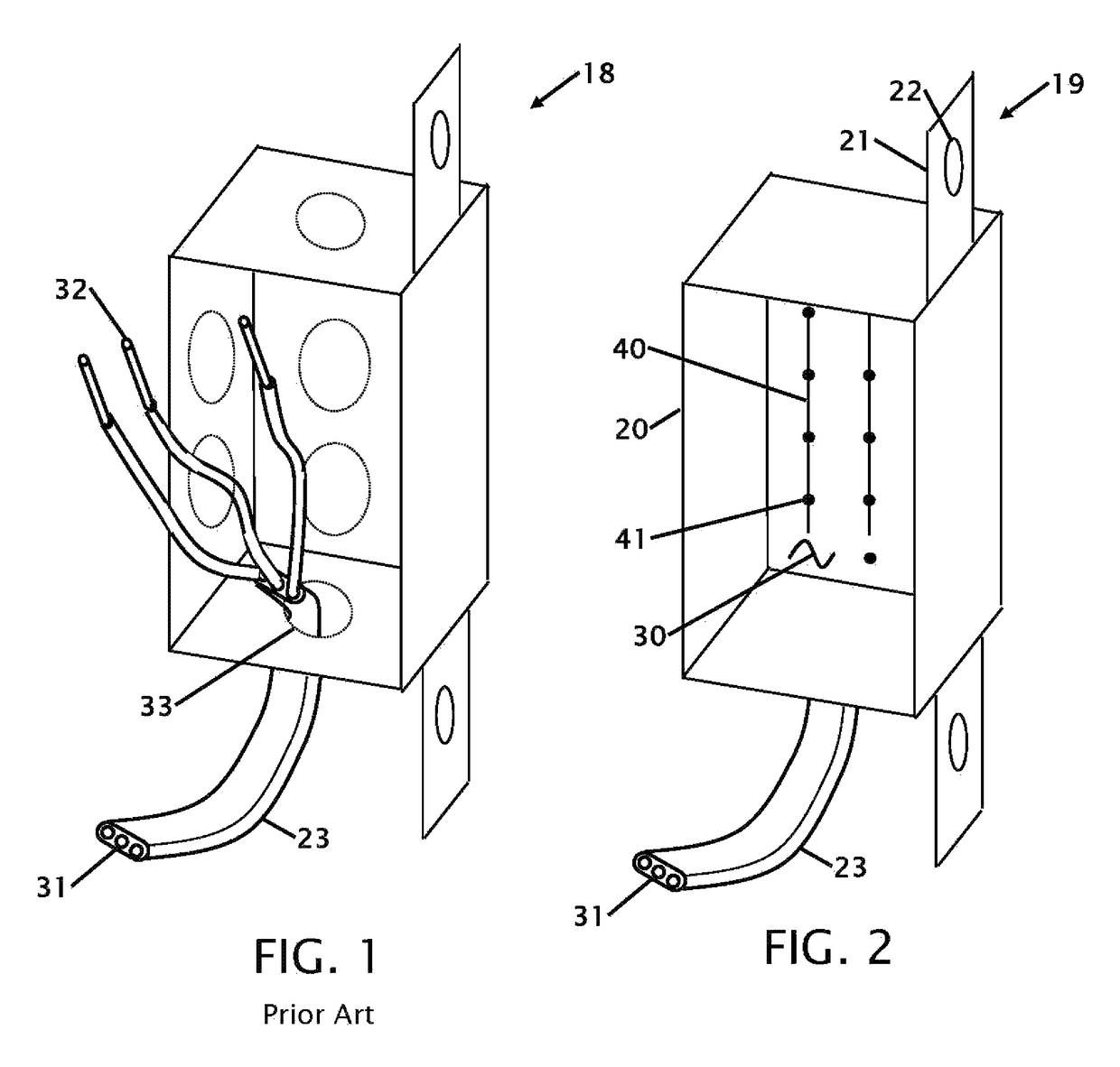
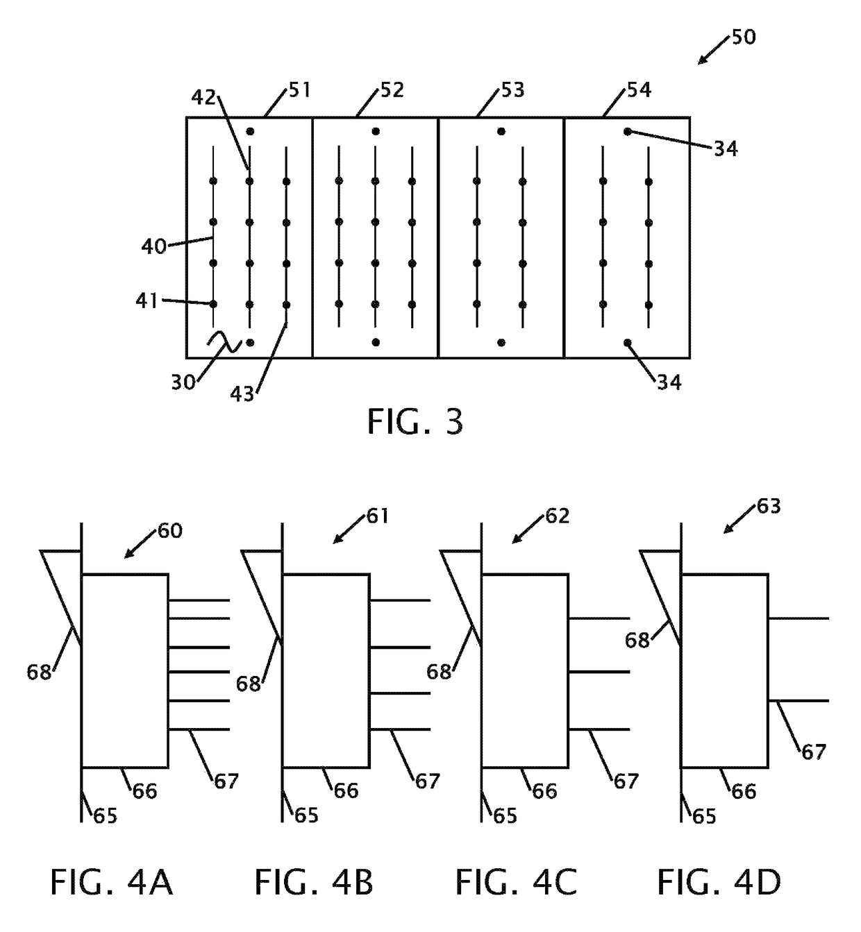
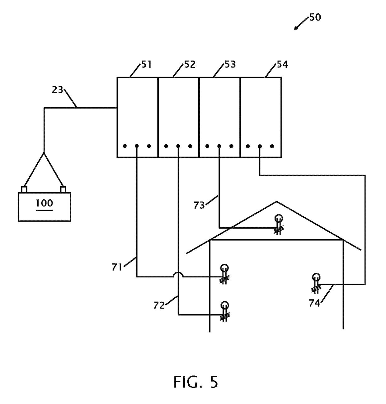
[0041]18 junction box (Prior Art)[0042]19 junction box[0043]20 junction box sides[0044]21 tab(s)[0045]22 hole[0046]23 jacketed wire[0047]30 circuit board[0048]31 conductor[0049]32 wire[0050]33 hole[0051]34 threaded hole[0052]40 trace[0053]41 contact[0054]42 contact[0055]43 contact[0056]44 connections[0057]45 conn...


PUM


Abstract

Improvements to an electrical junction box is disclosed. The junction box is configured with integrated connections in the back of the junction box. Switches and outlets have tabs in specific locations that align with the desired integrated connections to provide the desired function. All of the outlets and switches align parallel with the back and front of the junction box. The junction box is configurable to accept a single switch, dimmer switch, 3-way or outlet to many more than one function. In addition, the function of a junction box can be easily changed as long as the wiring has been connected to the new junction box. Installation and changes can be made in seconds instead of minutes. The depth of the internal distribution receptacle is adjustable within the adjustable electrical box to accommodate the thickness of the outlet or switch.

Description

CROSS REFERENCE TO RELATED APPLICATIONS[0001]This application is a continuation-in-part of applicant's application Ser. No. 62 / 547,969 filed Aug. 21, 2017 the entire contents of which is hereby expressly incorporated by reference herein.STATEMENT REGARDING FEDERALLY SPONSORED RESEARCH OR DEVELOPMENT[0002]Not ApplicableTHE NAMES OF THE PARTIES TO A JOINT RESEARCH AGREEMENT[0003]Not ApplicableINCORPORATION-BY-REFERENCE OF MATERIAL SUBMITTED ON A COMPACT DISC[0004]Not ApplicableBACKGROUND OF THE INVENTION[0005]Field of the Invention[0006]This invention relates to improvements in an electrical junction box. More particularly, the present junction box is for 110-volt electrical junction boxes, light switches, duplex outlets and trim plates with an integrated connection circuit that allows an installer to install electrical outlets, switches and a variety of other common electrical control devices into an electrical junction box without securing a free wire to an electrical device or requ...

Claims


Application Information

Patent Timeline
Patent Type & Authority Patents(United States)
IPC IPC(8): H01R4/2483H02G3/08H01R9/24H02G3/16H01R25/00H02G3/12H01R24/76H01R13/514H01R13/70H01R103/00
CPCH01R24/76H01R25/006H02G3/121H02G3/16H01R9/2408H02G3/086H01R13/70H01R2103/00H01R4/2483H01R13/514H01R24/78H01R13/741
Inventor REULMAN, SR., DAVID MARK
Owner REULMAN SR DAVID MARK
Why Eureka
Try Eureka