
Unmanned aerial vehicle communication using distributed antenna placement and beam pointing

a technology for unmanned aerial vehicles and beam pointing, which is applied in the field of unmanned aerial vehicle communication using distributed antenna placement and beam pointing, and can solve problems such as preventing improvement, preventing improvement, and many underdeveloped areas not having access to broadband services

Active Publication Date: 2019-01-22
BRIDGEWEST FINANCE LLC
View PDF20 Cites 0 Cited by
  • Summary
  • Abstract
  • Description
  • Claims
  • Application Information

AI Technical Summary

Benefits of technology

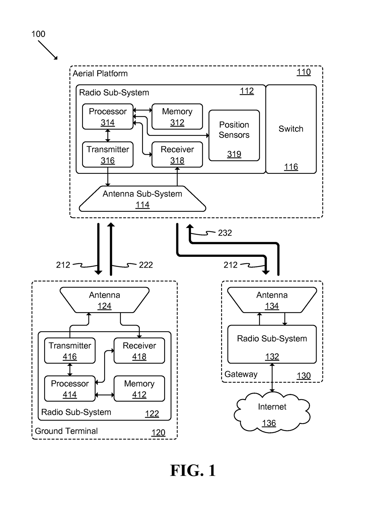
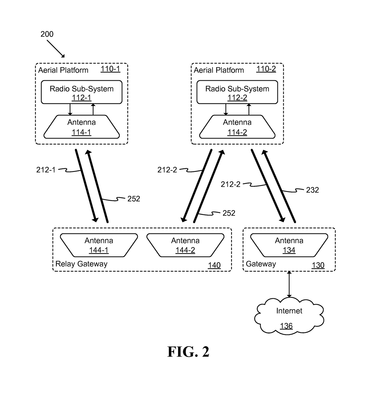
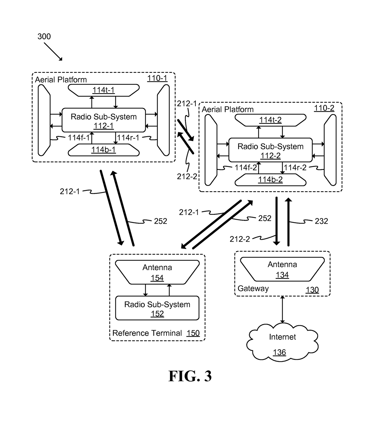
This patent describes a communication system that includes a gateway, ground terminals, and aerial platforms. Each aerial platform can communicate with the gateway and other aerial platforms using radio frequencies, making it possible for data to be exchanged between them. This system allows for seamless connectivity and communication between different parts of the network, improving efficiency and reliability.

Problems solved by technology

Many underdeveloped areas may not have access to broadband services such as satellite location services.
Infrastructure expenses may prevent improvement in such areas.
One issue is a lack of service in remote and lightly populated areas.
Poorer areas of the world, however, such as Africa lack adequate satellite capacity.
A notable reason satellite capacity has not been adequately provided in poor regions of the world is the relatively high cost of satellite systems.
Due to adverse atmospheric effects in satellite orbits, satellite hardware must be space qualified and is costly.
Launch vehicles to put the satellites in orbit are also costly.
Moreover, due to the launch risk and high cost of satellites, there is a significant cost to insure the satellite and the launch.
Therefore, broadband satellite systems and services are relatively costly and difficult to justify in poor regions of the world.
It is also costly to deploy terrestrial systems such as fiber or microwave links in lightly populated regions.
The small density of subscribers does not justify the deployment cost.

Method used


Image

  • Unmanned aerial vehicle communication using distributed antenna placement and beam pointing
  • Unmanned aerial vehicle communication using distributed antenna placement and beam pointing
  • Unmanned aerial vehicle communication using distributed antenna placement and beam pointing

Examples


Embodiment Construction

[0020]The following detailed description is of the best currently contemplated modes of carrying out exemplary embodiments of the invention. The description is not to be taken in a limiting sense, but is made merely for the purpose of illustrating the general principles of the invention, as the scope of the invention is best defined by the appended claims.

[0021]Various inventive features are described below that can each be used independently of one another or in combination with other features. Broadly, some embodiments of the present invention generally provide a way to communicate among a set of aerial platforms and a set of ground terminals.

[0022]A first exemplary embodiment provides a communication system including: at least one gateway able to provide broadband connectivity; a set of ground terminals; and a set of aerial platforms, where at least one aerial platform is able to communicate with at least one gateway using radio frequencies, each aerial platform is able to commun...


PUM


Abstract

A communication system is described. The system includes: at least one gateway able to provide broadband connectivity, a set of ground terminals, and a set of aerial platforms, where at least one aerial platform is able to communicate with at least one gateway using radio frequencies, each aerial platform is able to communicate with ground terminals using radio frequencies, and each aerial platform is able to communicate with each other aerial platform using radio frequencies. An automated method for determining a beam direction for communication among UAVs includes: dividing a space around the UAV into multiple sub-regions, and, iteratively: selecting a sub-region from among the multiple sub-regions; pointing a signal toward the sub-region; and determining whether a signal is received from another UAV, until all sub-regions from among the multiple sub-regions have been selected.

Description

CROSS-REFERENCE TO RELATED APPLICATIONS[0001]This application claims priority to U.S. Provisional Patent Application Ser. No. 61 / 940,805, filed on Feb. 17, 2014, and U.S. Provisional Patent Application Ser. No. 61 / 946,575, filed on Feb. 28, 2014.BACKGROUND OF THE INVENTION[0002]Many underdeveloped areas may not have access to broadband services such as satellite location services. Infrastructure expenses may prevent improvement in such areas.[0003]Many aerial platforms such as airplanes and drones or Unmanned Aerial vehicles (UAVs) have been or will be deployed in various regions around the world for broadband access. Such platforms may be deployed in a more cost effective manner than typical satellite networks.[0004]As internet traffic has increased over the years, new technologies are needed to deliver broadband access to homes and enterprises at lower cost and to places that are not yet covered. Examples of current broadband delivery systems include terrestrial wired networks suc...

Claims


Application Information

Patent Timeline
Patent Type & Authority Patents(United States)
IPC IPC(8): H04B7/185H04W84/06B64C39/02H04W36/30H04W24/02H04B7/155H04W36/36H04W36/00H04W48/16H04W88/16H04W84/00H04W36/12
CPCH04B7/18504H04B7/1555H04B7/18506H04B7/18528H04B7/18539H04B7/18541H04B7/18543H04B7/18554H04B7/18578H04W24/02H04W36/0005H04W36/0083H04W36/30H04W36/36H04W84/06B64C39/024Y02D70/446B64C2201/122H04W36/0016H04W36/12H04W48/16H04W84/005H04W88/16Y02D70/00Y02D70/1242Y02D70/1262Y02D70/142Y02D70/164Y02D30/70H04B7/18556H04W36/0085B64U2101/20B64U80/30H04W36/304
Inventor JALALI, AHMAD
Owner BRIDGEWEST FINANCE LLC
Learn More