
Brake disc

a technology of brake discs and cylinders, applied in the direction of brake discs, brake elements, braking members, etc., can solve the problems of weak structural strength, serious abraded outer edges of the recess, and inability to use the brake discs, and achieve the effect of preferable structural strength

Active Publication Date: 2019-01-29
WEN YUAN HUNG
View PDF40 Cites 2 Cited by
  • Summary
  • Abstract
  • Description
  • Claims
  • Application Information

AI Technical Summary

Benefits of technology

The present invention provides a brake disk with the benefits of both a floating brake disk and a structurally strong brake disk. The brake disk is designed to prevent the inner and outer disks from rotating relative to each other, and to prevent heat from transmitting to the inner disk through the positioning member. The technical effects include improved performance and durability of the brake disk.

Problems solved by technology

However, in this type of structure, the heat produced during the braking process transmits through the brake disk to the hub and influences the function of a brake.
In addition, the inner and outer disks are fixed to each other only by the positioning member, so the structural strength is weak.
If there are dimensional errors, the brake disk will be unusable.
In addition, after being used for a long time, an outer edge of the recess may be abraded seriously, and the structural strength and stability of the brake disk may be influenced.
However, the opening of the recessed portion of the inner disk is smaller than the maximum width of the protruding portion of the outer disk, so the protruding portion cannot enter the recessed portion along the radial direction.
Thus, it is inconvenient that the inner disk can only be installed onto the outer disk along the axial direction.
As a result, too much stress concentrates on the intersection of the two legs.

Method used


Image

  • Brake disc
  • Brake disc
  • Brake disc

Examples


Embodiment Construction

[0022]The present invention will be clearer from the following description when viewed together with the accompanying drawings, which show, for purpose of illustrations only, the preferred embodiment in accordance with the present invention.

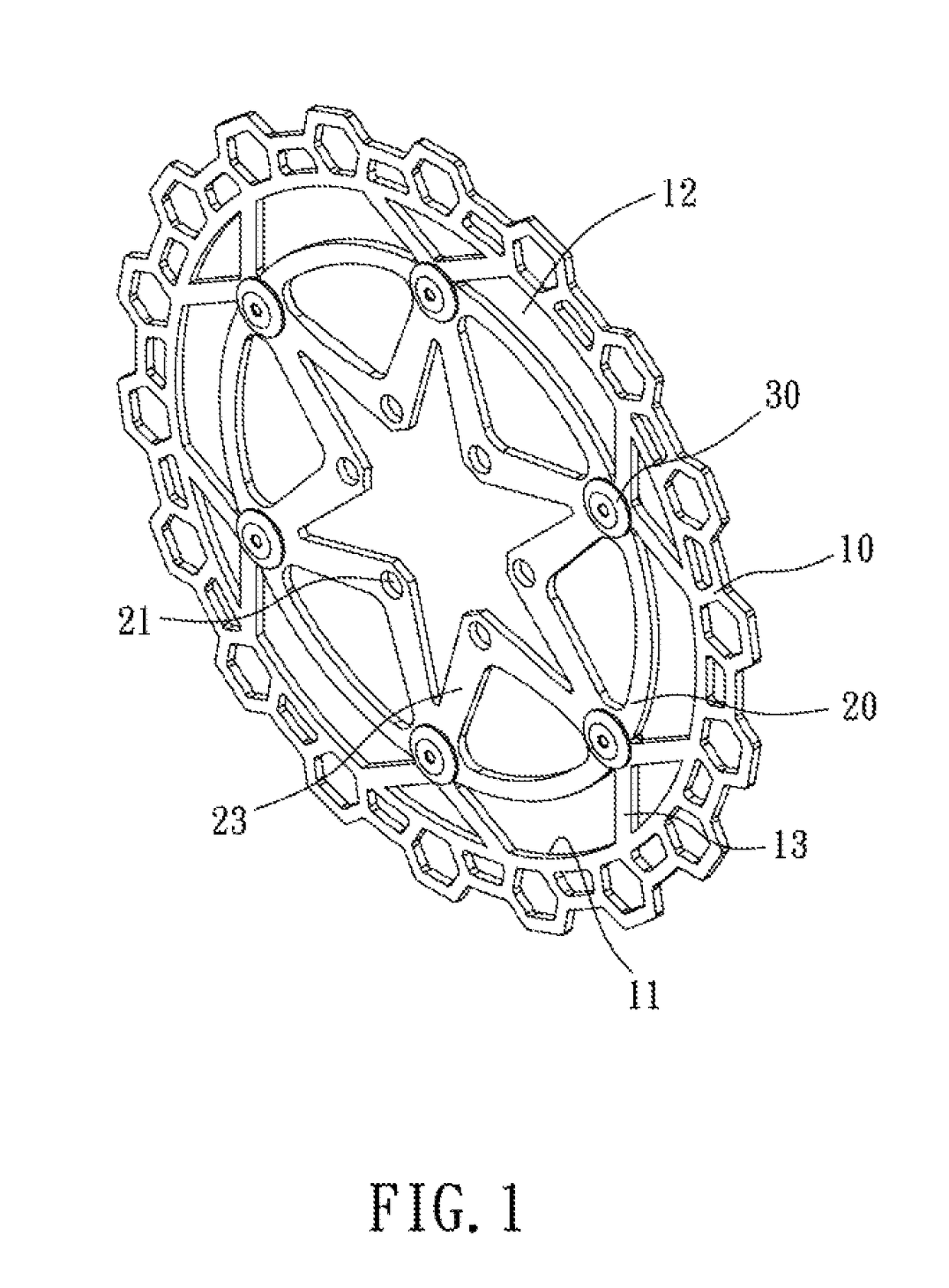
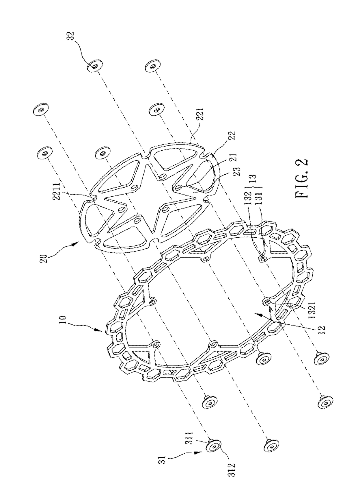
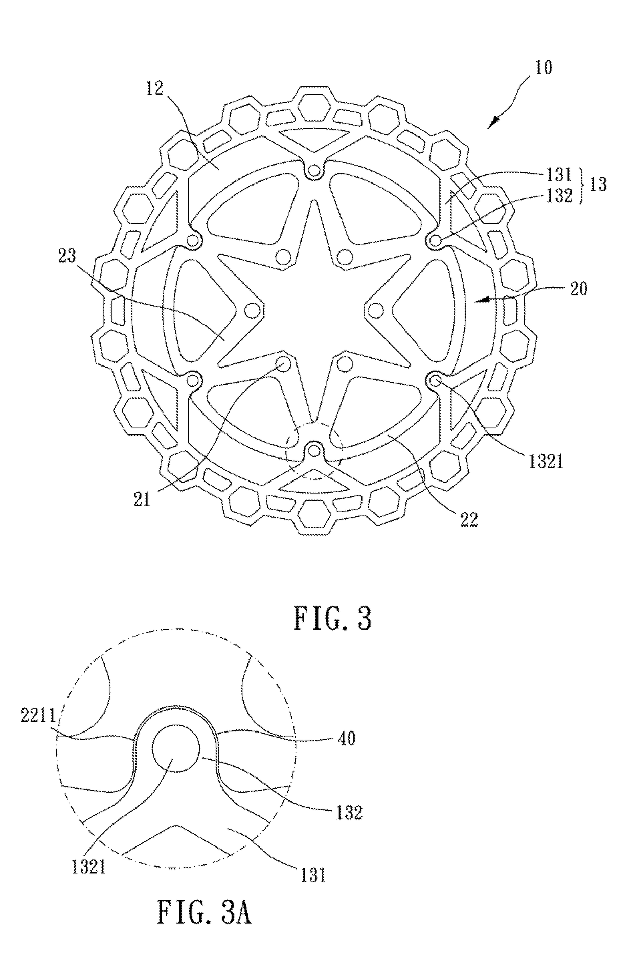
[0023]Please refer to FIGS. 1 to 5 for a brake disk, including an outer disk 10, an inner disk 20 and a plurality of positioning members 30.

[0024]The outer disk 10 is substantially ring-shaped, and a through hole 12 is defined in a center thereof. The through hole 12 defines a central axis, and the central axis defines an axial direction. The outer disk 10 has an inner annular flange 11, and the inner annular flange 11 surrounds the through hole 12. The inner annular flange 11 of the outer disk 10 is formed with a plurality of connecting bridges 13 arranged in intervals, and each said connecting bridge 13 extends radially toward the central axis of the through hole 12. An end of the connecting bridge 13 remote from the inner annular flange 11 of ...


PUM


Abstract

A brake disk includes: an outer disk, being substantially ring-shaped and defining a central axis, an inner annular flange of the outer disk formed with connecting bridges, the connecting bridge having a protruding portion disposed through a disposing hole axially; an inner disk, coaxially disposed in the outer disk and located on a same plane with the outer disk, an outer annular flange of the inner disk formed with recessed portions corresponding to the protruding portions respectively, the protruding portion fittingly engaged with the recessed portion to prevent the inner disk from rotating relative to the outer disk, the recessed portion and the protruding portion having a gap therebetween; a plurality of positioning members, each positioning member disposed through the disposing hole to restrain the outer and inner disks from moving relatively axially; wherein the outer and inner disks are axially non-overlapping.

Description

CROSS REFERENCE TO RELATED APPLICATIONS[0001]This application is a Continuation-in-Part of co-pending application Ser. No. 14 / 863,103, filed on Sep. 23, 2015, for which priority is claimed under 35 U.S.C. § 120; and this application claims priority of Application No. 103142457 filed in Taiwan on Dec. 5, 2014 under 35 U.S.C. § 119, the entire contents of all of which are hereby incorporated by reference.BACKGROUND OF THE INVENTION[0002]Description of the Prior Art[0003]Conventionally, a brake disk is single-piece. An outer ring of the brake disk is for a caliper to clamp thereon to brake, and a central portion of the brake disk is for being comovably connected with a hub. However, in this type of structure, the heat produced during the braking process transmits through the brake disk to the hub and influences the function of a brake.[0004]Therefore, a two-piece brake disk is provided, including an inner disk for being connected with a hub and an outer disk for a caliper to clamp ther...

Claims


Application Information

Patent Timeline
Patent Type & Authority Patents(United States)
IPC IPC(8): F16D65/12F16D65/02
CPCF16D65/12F16D65/128F16D65/123F16D2065/1392F16D2065/1316F16D2065/1364F16D2065/1312
Inventor WEN, YUAN-HUNG
Owner WEN YUAN HUNG
Learn More