Eureka AIR delivers breakthrough ideas for toughest innovation challenges, trusted by R&D personnel around the world.

Brewing unti with a water heater

a technology of brewing unit and water heater, which is applied in beverage vessels, household appliances, kitchen equipment, etc., can solve the problems of cumbersome structure and achieve the effect of compact and simple manufacturing

Active Publication Date: 2019-02-12
VERSUNI HLDG BV
View PDF18 Cites 1 Cited by
  • Summary
  • Abstract
  • Description
  • Claims
  • Application Information

AI Technical Summary

Benefits of technology

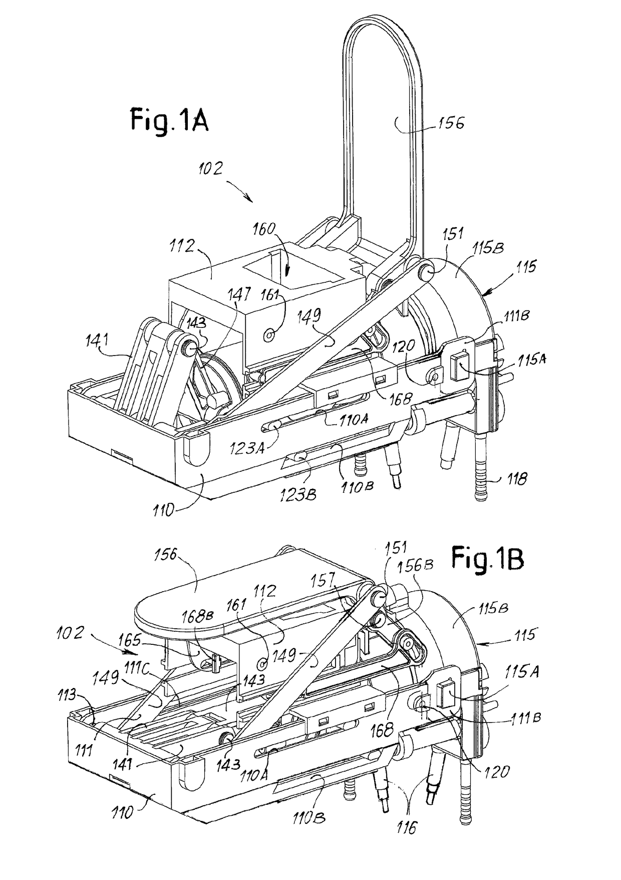
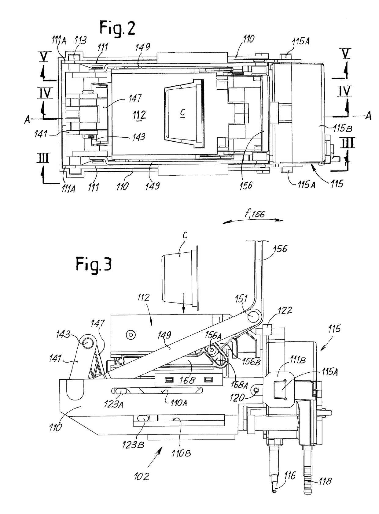
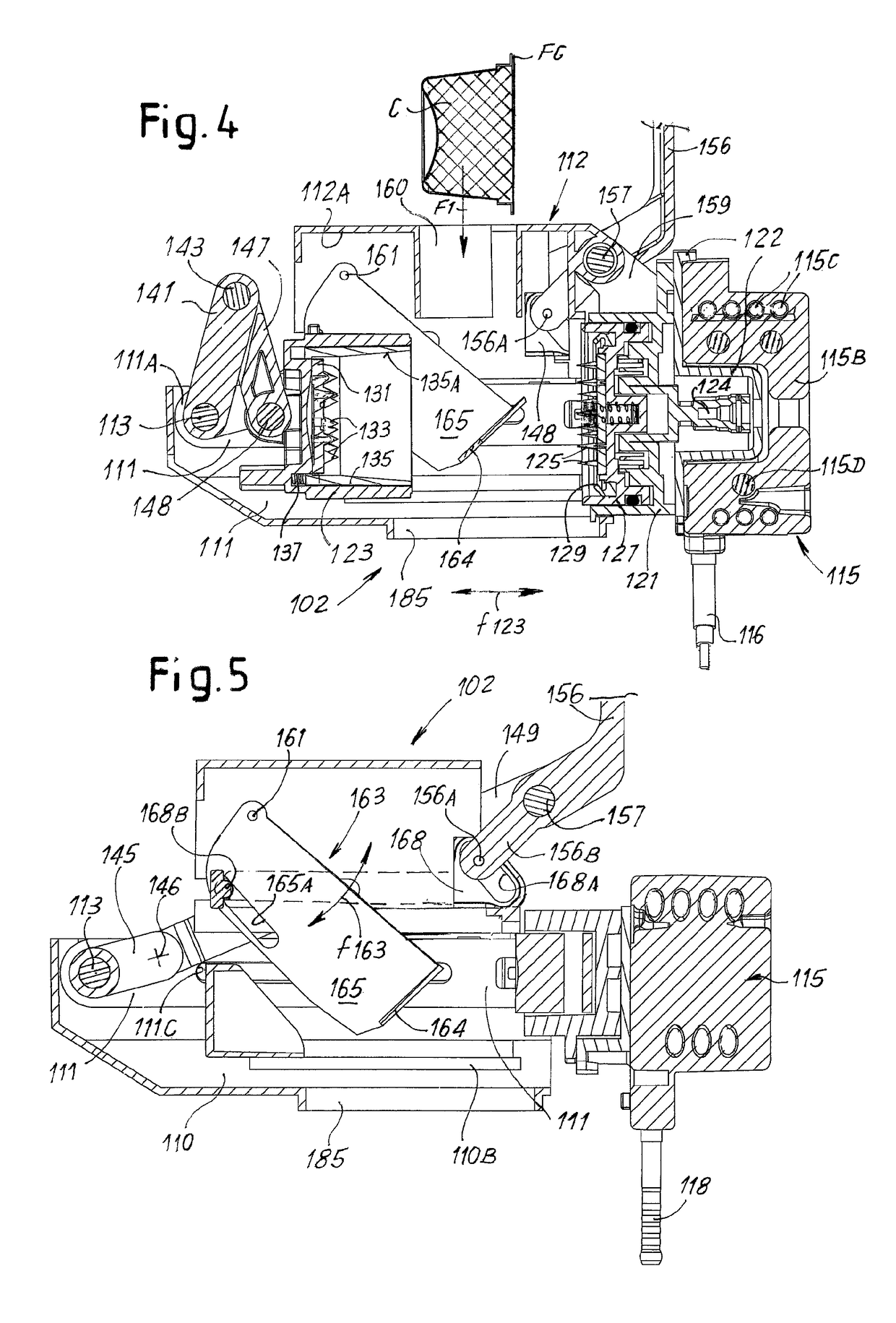
[0009]The present invention relates to a brewing unit with a brewing chamber formed by at least two portions mobile one with respect to the other, which at least alleviates the above mentioned problem. The object of preferred embodiments of the invention is to provide a brewing unit which is particularly compact and simple to manufacture.
[0012]The closed structure formed by the first brewing chamber portion, the side components and the second end component can be manufactured and assembled with reduced tolerances, so that the brewing chamber portions can operate correctly. Precise dimensioning and reduced clearances result in improved guided movement of the brewing chamber portions. Correct water-tight closure of the brewing chamber and / or waterproof sealing action against the capsule arranged in the brewing chamber is thus ensured, preventing water and / or beverage leakage during the brewing cycle.
[0013]Since the water heater is connected to the side components separately from the brewing chamber portions, the water heater does not require precise manufacturing. The water heater can be connected to the remaining components of the structural frame with a rather coarse connection. Possible clearances between the closed structure formed by the side components and the first brewing chamber portion on the one side and the water heater on the other can be taken up during brewing thanks to elastic deformations. During brewing the first brewing chamber portion is pressed by the pressurized water against the adjacent water heater. Possible clearances are taken up and the water heater contributes to maintain the brewing chamber closed against the pressure exerted therein by the pressurized brewing water. In other words, the water heater body contributes to the mechanical resistance of the structural frame of the brewing unit forming part thereof, due to the fact that the forces generated by the pressurized water in the brewing chamber are at least partly supported by the water heater body. This renders the structure more economical and efficient.
[0014]Relatively sturdy constraining members can be used to connect the water heater to the side components of the closed structure, while the brewing chamber portions can be connected to the side components by means of lighter, less expensive but sufficiently precise constraining members.
[0018]In some embodiments the water heater comprises a main body and protrusions engaging into seats provided in side components of the structural frame. This provides a simple though efficient and sturdy connection between the side components and the water heater, capable of withstanding high pressure inside the brewing chamber.
[0019]In some embodiments the side components of the structural frame form guides for slidingly engage the movable brewing chamber portion. This reduces the number of components forming the brewing unit, since the same side components perform different functions.

Problems solved by technology

One problem of these brewing units, being of the type using pre-packaged single-dose capsules, or loose ingredients, is connected with the need of providing a structure surrounding the brewing chamber which is capable of resisting high mechanical stresses generated by the pressurized water fed through the brewing chamber.
This requires cumbersome structures.

Method used


Image

  • Brewing unti with a water heater
  • Brewing unti with a water heater
  • Brewing unti with a water heater

Examples


Embodiment Construction

[0050]The following detailed description of the exemplary embodiments refers to the accompanying drawings. The same reference numbers in different drawings identify the same or similar elements. Additionally, the drawings are not necessarily drawn to scale. Also, the following detailed description does not limit the invention. Instead, the scope of the invention is defined by the appended claims.

[0051]Reference throughout the specification to “one embodiment” or “an embodiment” or “some embodiments” means that the particular feature, structure or characteristic described in connection with an embodiment is included in at least one embodiment of the subject matter disclosed. Thus, the appearance of the phrase “in one embodiment” or “in an embodiment” or “in some embodiments” in various places throughout the specification is not necessarily referring to the same embodiment(s). Further, the particular features, structures or characteristics may be combined in any suitable manner in one...


PUM


Abstract

A brewing unit includes a brewing chamber with first and second brewing chamber portions movable one with respect to the other, and a water heater. Further, the brewing unit includes a structural frame supporting the two brewing chamber portions, and on which forces generated by the pressurized water in the brewing chamber during brewing are discharged. The structural frame includes two side components arranged sideways of the brewing chamber, and two end components mechanically constrained to the side components. One of the two end components includes the first brewing chamber portion. Further, the side components and the end components form a closed structure, whereto the water heater is in turn constrained independently, with separate constraining members, from the first brewing chamber portion and adjacent thereto, outside the closed structure. The forces generated by the pressurized water in the brewing chamber during brewing are also discharged on the water heater.

Description

CROSS-REFERENCE TO PRIOR APPLICATIONS[0001]This application is the U.S. National Phase application under 35 U.S.C. § 371 of International Application No. PCT / IB2012 / 053403, filed on Jul. 4, 2012, which claims the benefit of U.S. Provisional Patent Application No. 61 / 506,244, filed Jul. 11, 2011 and European Patent Application No. 11173201.2, filed on Jul. 8, 2011. These applications are hereby incorporated by reference herein.TECHNICAL FIELD[0002]The present invention relates to a brewing unit for producing drinks such as coffee, from loose coffee powder or single-dose packagings, such as capsules or pods.BACKGROUND ART[0003]For producing hot drinks, such as for example coffee, tea, vegetable-based infusions and the like, single-dose packagings, in the form of so-called capsules, pods, cartridges or the like are often used. Here after the term “capsule” will be used to broadly designate such a single-dose packaging. It shall be understood that, unless specifically indicated, said te...

Claims


Application Information

Patent Timeline
Patent Type & Authority Patents(United States)
IPC IPC(8): A47J31/36A47J31/60A47J31/54
CPCA47J31/36A47J31/3633A47J31/3638A47J31/60A47J31/54A47J31/542A47J31/3676
Inventor BALDO, MASSIMOSANTINI, MARCO
Owner VERSUNI HLDG BV
Why Eureka
Eureka Blog
Learn More