Slip-ring unit

a technology of ring unit and ring, which is applied in the direction of current collector, rotary current collector, electrical apparatus, etc., can solve the problems of inconvenient system transmission of high-frequency digital signals, and achieve the effect of soft slip conta

Active Publication Date: 2013-01-08
LTN SERVOTECHN +1
View PDF11 Cites 11 Cited by
  • Summary
  • Abstract
  • Description
  • Claims
  • Application Information

AI Technical Summary

Benefits of technology

[0011]The type of construction described herein provides a particularly advantageous assemblage such that a slip-ring unit that is compact and simple to manufacture makes it possible to transmit a various types of electrical voltages, in particular currents and digital signals, in a rotatable manner, an effective shielding being ensured for the transmission of the signals. Accordingly, the shielded potential is also transmitted over shielded lines that are rotatable relative to each other.
[0020]Either the second brush element or the third brush element or both brush elements may be arranged as a hollow body. For this purpose, one of the brush elements or both brush elements may be configured such that the respective brush element or the brush elements have radially springy properties. In particular, the second brush element or the third brush element or both may have radially spring-loaded tabs. Alternatively, the second brush element or the third brush element or both brush elements may also be arranged as flat spiral springs having a cycloid-like geometry so as to allow for a comparatively soft slip contact.

Problems solved by technology

Such systems are not suitable, however, for reliably transmitting high-frequency digital signals, which are normally transmitted in shielded lines, in addition to the analog currents from the brush wires to a slip ring rotating relative to the brush wires.

Method used


Image

  • Slip-ring unit
  • Slip-ring unit
  • Slip-ring unit

Examples


Embodiment Construction

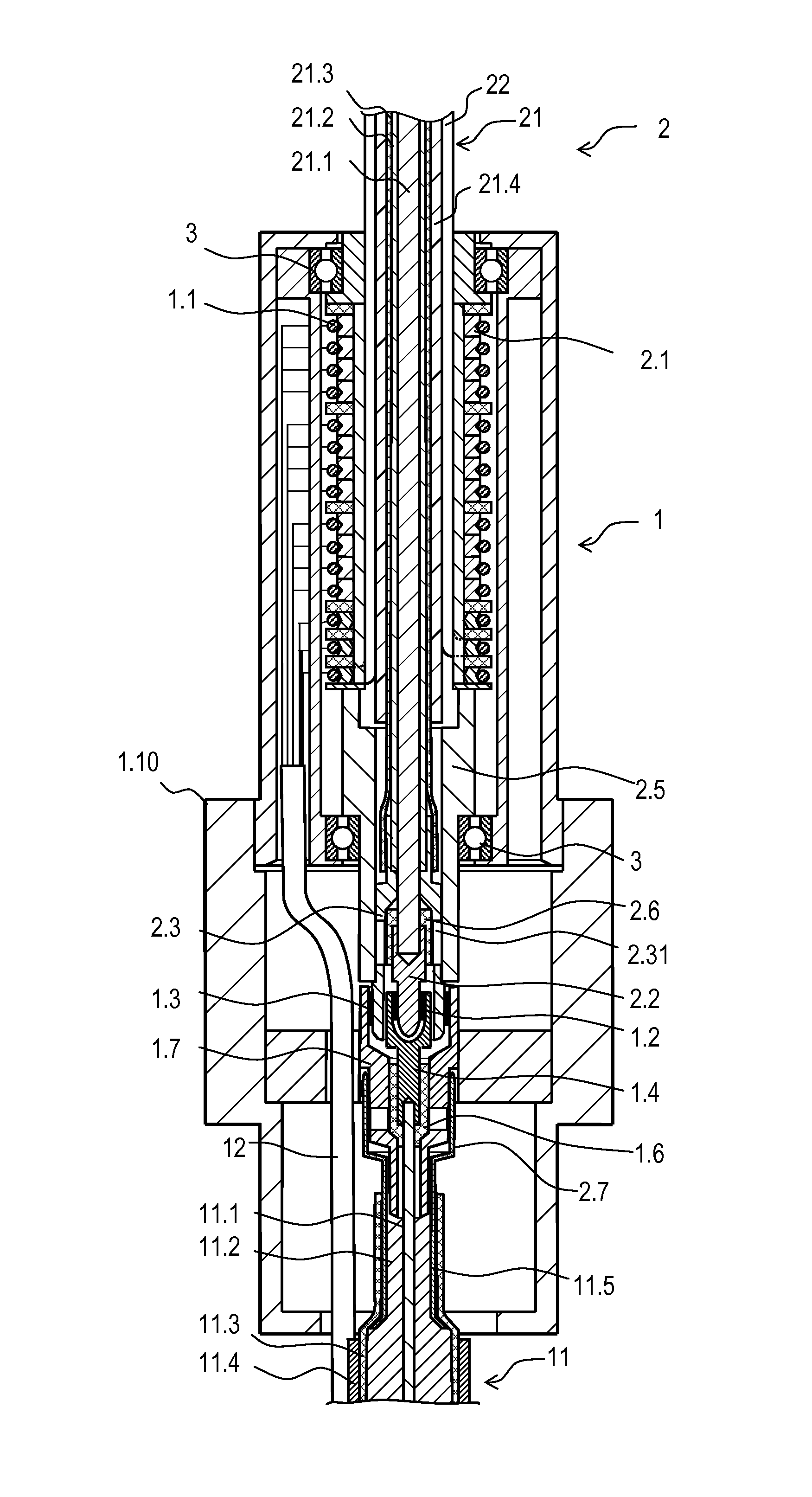
[0032]The slip-ring unit of the exemplary embodiment is used to transmit electrical voltages, in the present case analog currents and digital signals in particular, such that for example a rotatable electronic camera may be connected to a stationary unit. The analog currents are for example currents for moving actuating motors, e.g. of a zoom drive, and currents for operating the electronics of the camera. For the transmission of images, the camera supplies high-frequency digital signals, which may likewise be transmitted by the slip-ring unit in an interference-free manner.

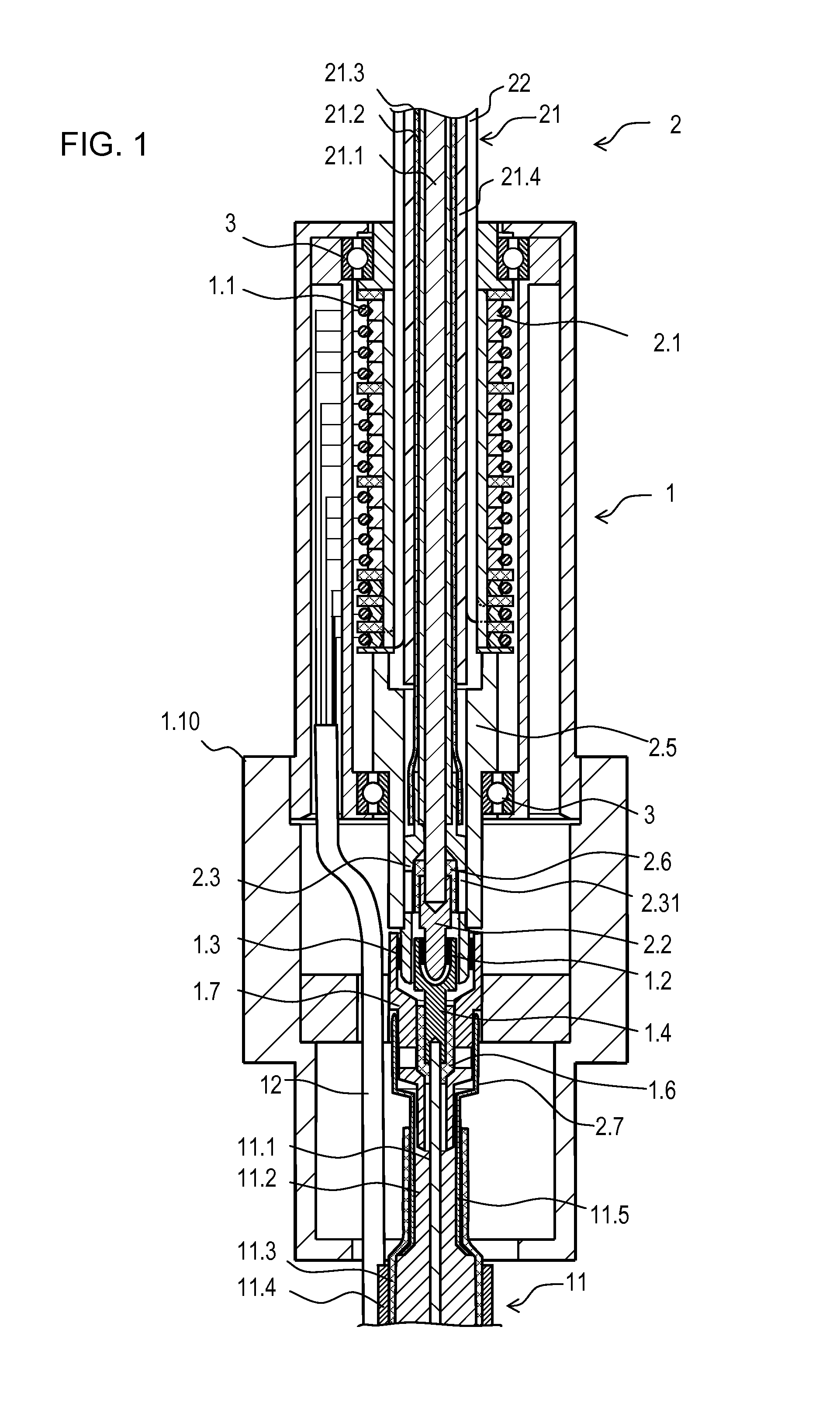
[0033]As shown in FIG. 1, the slip-ring unit has a stator 1 and a rotor 2. Rotor 2 is disposed in a rotatable manner relative to stator 1 with the aid of bearings 3. Among other things, a first cable 21, which is arranged as a so-called coaxial cable, extends in rotor 2, concentrically to the axis of rotation (see also FIG. 3). First cable 21 is used to transmit the digital signals, which have a frequency in the ...


PUM


Abstract

In a slip-ring unit for electrically connecting two components that are rotatable relative to each other, one component is arranged as a first cable, which has a core and a shield. The slip-ring unit includes first, second and third brush elements as well as first, second and third slip bodies. The first slip body has an opening extending through it axially, through which a first cable extends for transmitting the voltage applied on the core. The second brush element is additionally disposed at a radial offset with respect to the third brush element.

Description

FIELD OF THE INVENTION[0001]The present invention relates to a slip-ring unit for electrically connecting two components that are rotatable relative to each other.BACKGROUND INFORMATION[0002]Slip-ring units are frequently made up, inter alia, of a slip-ring brush and slip bodies, in particular slip rings, the slip-ring brush having sliding contact with rotating slip rings during operation. Such slip-ring units are used in many technical fields for transmitting electrical voltages, in particular signals or electrical power, for example, from a stationary electrical unit to a rotating electrical unit. For this purpose it is important that a sound and continuous contact is provided between the slip-ring brush and the slip rings, for example via spring-loaded brush elements.[0003]For rotatably connecting electronic cameras, for example, it may be necessary that both high-frequency digital image signals as well as analog currents, such as the current supply of the camera, are reliably tr...

Claims


Application Information

Patent Timeline
Patent Type & Authority Patents(United States)
IPC IPC(8): H01R39/00
CPCH01R39/64H01R9/05
Inventor ANGERPOINTNER, LUDWIGFRIESE, NORBERT
Owner LTN SERVOTECHN
Why Eureka
Try Eureka